Exploded view > Bewegungsart > Conc 
Use this function to define concentric movements in exploded views while the Exploded view mode is active. This makes sense if, for instance, you want to transform parts that are arranged concentrically around a common centre, e.g. bolts arranged on a polar or radial grid.
In the case of parts that are arranged symmetrically around a common centre, the centroids of the parts are located on a circle. The Concentricity function moves the parts in such a way that their centroids will be located on a circle that is concentric to the aforementioned circle.
Please note:
When using the Concentricity transformation, the centroid of each selected part will be considered, that is, the transformation always refers to the parts that were explicitly selected. For instance, a selection of parts arranged symmetrically around a common centre and forming an assembly will produce a different result than a selection of the sub-parts when applying the concentricity transformation to them. If you select the assembly, only the centroid of the assembly will be considered, and not the centroids of the sub-parts.
Also, an appropriate common centre must be selected for this type of transformation; otherwise, you may not obtain the desired results.
When you call the function, the Move (concentric) dialogue window will be displayed:
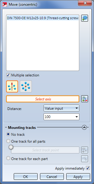
Proceed as follows:
- In the next step you determine the settings for the concentric transformation. Click on the corresponding symbol to determine how the transformation should be performed, and choose the type of the distance determination.
 Concentric, about axis
Here the transformation takes place by selection of an axis. The moved parts will then be located on a circle the centre point of which lies on the selected axis and runs through the centroids of the selected parts. This means that the parts move within one circle plane, i.e. the transformation is two-dimensional.
 Concentric, about point
If you choose this option, the parts will move on a straight line running through the selected point and the centroid of the corresponding part, i.e. the transformation is three-dimensional.
You can choose between 3 different methods for distance determination:
- Value input
The selected parts will be concentrically moved by a defined value.
If you have selected the Concentric, about axis option, the centroids of the original parts will be located on a circle the centre of which lies on the selected axis, with the parts being arranged symmetrically around a common centre. The concentricity function moves the parts in such a way that their centroids lie on a circle which is concentric to the original circle and has a defined distance to it. - 2 points
Here you determine the distance of the movements by 2 points.
If you have selected the Concentric, about axis option, the first point determines the radius of a circle the centre of which lies on the selected axis, and which is concentric to the circle running through the centroids of the selected parts. You can now enlarge or downsize this circle dynamically by moving the point with the cursor, moving the selected parts concentrically in this way. In the process, the direction of the parts may change or the parts may overlap. The circle determined by the first point will be displayed by a dashed circular line. You determine the distance of the movement by specifying a second point. If you choose a point on the dashed circle, the distance is 0.
If you have selected the Concentric, about point option, the first point determines a point on the displacement vector, and the second point determines the distance.
- Dynamic
Here you determine the distance dynamically with the cursor.
If you have selected the Concentric, about axis option, HiCAD automatically determines a circle which is concentric to the circle running through the centroids of the selected parts. You can dynamically enlarge or downsize the circle, moving the parts in the process. The distance will be determined by a point specification.
If you have selected the Concentric, about point option, HiCAD automatically determines a straight line running through the selected point and the centroid of a part. The selected parts can be moved along this straight line.
If the Select axis or Select point field has an orange border, you can directly determine the axis or point for the common centre of the selected parts. If this is not the case, click on the  symbol to select the axis, or on
  to select the point. The axis can be determined by selecting 2 points, an edge or a surface. In the case of a surface the axis will be determined by its surface normal.
Alternatively, to determine the axis or the point, you can also use the functions of the context menu, which you activate with a right-click.
- In the lower area of the dialogue window, you can determine whether mounting tracks are to be entered in the model drawing that mark the course of a transformation:
If the Apply immediately checkbox is active, the transformation will be immediately accepted - as shown in the preview - and entered into the explosion log, i.e. you do not have to click the Apply button. If further parts are selected immediately afterwards - without changing the other settings - the same transformation is carried out immediately for these parts without the parts appearing in the selection list.
If the checkbox is not active, then use buttons. If you click OK the transformation will be accepted and the dialogue window is closed. If you click Apply the current transformation will be accepted. Unlike OK, the dialogue window will not be closed here, so that further transformations can be defined. If you click Cancel the dialogue window will be closed. Transformations that have not yet been adopted are lost.
Each applied transformation will be logged in the Exploded view docking window. Exploded views can be subsequently edited via this log.
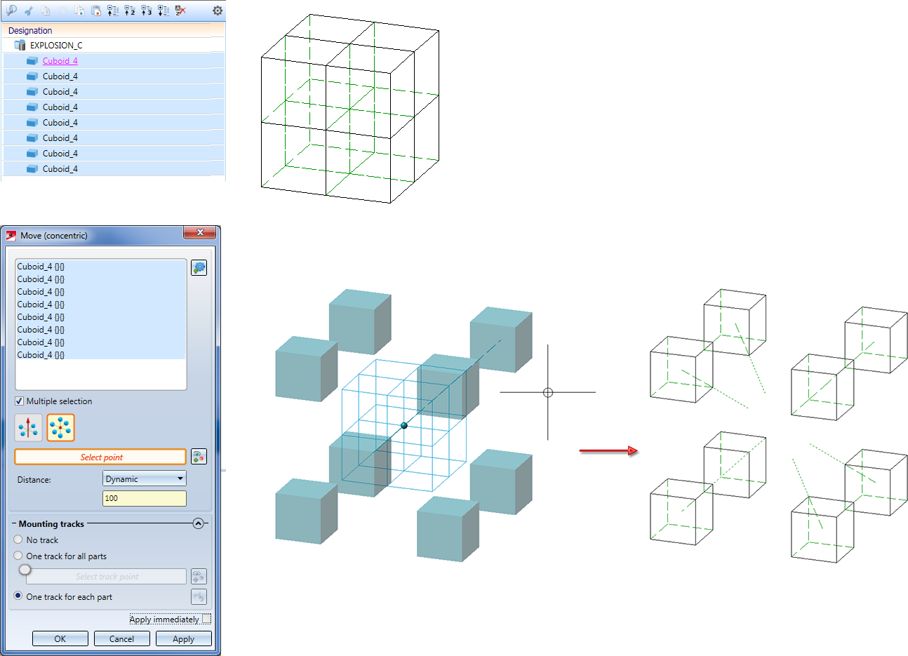
Example 1:
The following example illustrates the difference between the transformation types Concentric, about axis and Concentric, about point. The image below shows 8 neighbouring cuboids and one concentricity transformation about a point:
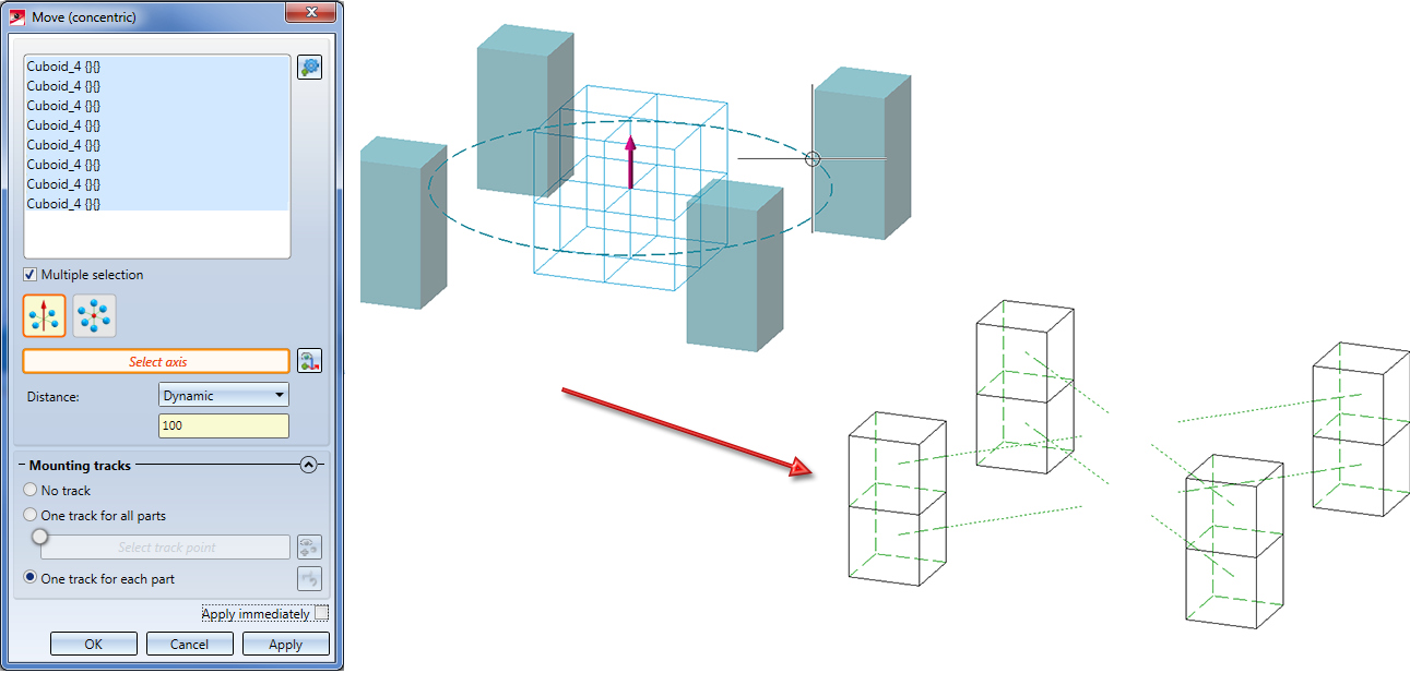
The next image shows the concentricity transformation about an axis:
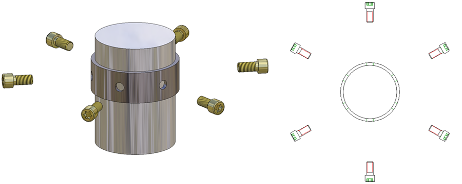
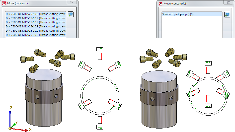
The image below shows bolts that are arranged on a radial grid and form an assembly.
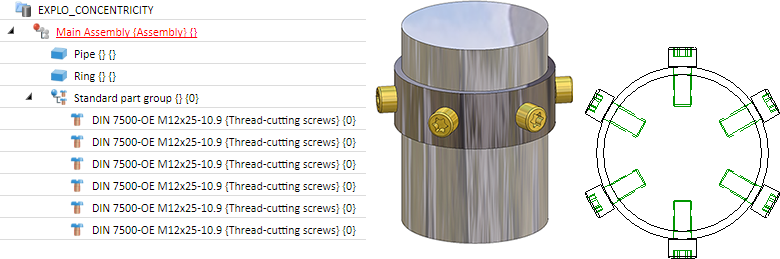
The next image shows an exploded view with a concentric movement of these bolts. Please note that the individual bolts and not the Standard part group assembly has been selected here. The Concentric, about axis option has been selected, and the chosen axis is the centre axis of the pipe. If you had selected the Standard part group assembly, the function would have no effect.
The next image shows an exploded view where the individual bolts have been selected, too, for the concentricity transformation. The difference here is that the X-axis has been selected as the common centre, which was not really a sensible choice here. If you has selected the Standard part group assembly here, this would have resulted in a "normal" transformation.
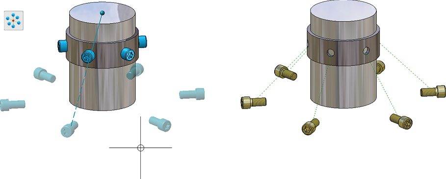
The following image shows a concentricity transformation of the same parts about a point:


Exploded View • Create Exploded View • Representation Functions