Project: HiCAD Steel Engineering
|
|
Please note:
|
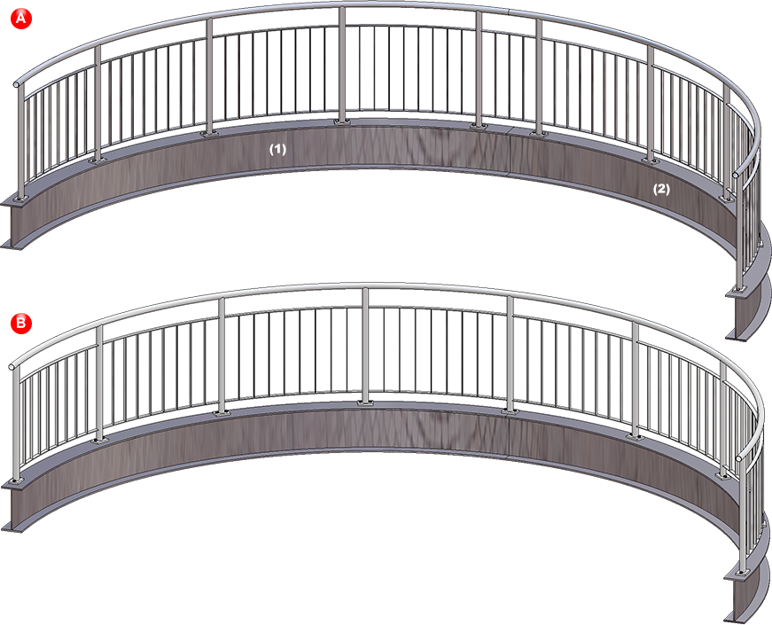
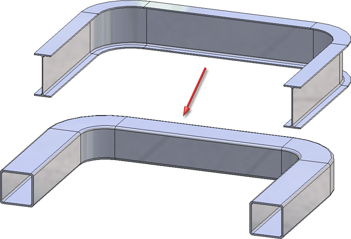
Curved segments with equal radius and mid point are now handled like aligned, straight beams. That is, if there are several curved beam segments with equal radius and mid point in succession, the railing elements of these beams will be combined into one segment assembly. In this way, continuous hand rails and knee rails will be created on these beams, too. The updating and modification of existing railings (before Version 2019 SP2 Patch 1) with such areas continues to take place with individual segment assemblies, i.e. non-continuous, "interrupted" hand rails and knee rails.
In the image below a railing along two curved beams (1) and (2) has been created. A shows the result with a version before 2019 SP2, Patch1, B shows the result with Patch 1.
The HiCAD Parameter configuration for Steel/Metal Engineering have been changed, with the aim to make Steel Engineering workshop drawings clearer and better intelligible.
The following modifications have been applied:
BOMs
|
Setting |
previous |
as of SP2 |
Parameters |
|---|---|---|---|
|
Insertion of BOMs |
Quantity list in view group |
Quantity list in drawing frame |
Changed in Configuration Editor for all Usages Automatic drawing derivation > Production drawing > Usage-dependent > ... > View group > Insert BOM |
|
Position of BOMs in drawing frame |
bottom right |
bottom left |
Changed in Configuration Editor for all Usages Automatic drawing derivation > Production drawing > Usage-dependent > ... > View group > BOM: Position in view group |
|
Display of columns DSTV, Part type, Designation |
yes |
no |
Changed in the hicad_stahlbau.rms in the HiCAD directories sys and sys/BOMTemplates.
|
Font size
|
Setting |
previous |
as of SP2 |
Parameters |
|---|---|---|---|
|
Item numbers of sub-parts |
5 |
3.5 |
Adjusted in the templates ofthe FTD file for annotations |
|
Height of weld symbols |
3.5 |
2 |
Changed in Configuration Editor Drawing > Annotations > Weld symbols > Symbol height
|
|
Identificatiopn of sections |
5 |
4 |
Changed in Configuration Editor Drawing > Views > Ident > Sections > Font height in original view |
View shortening
|
Setting |
previous |
as of SP2 |
Parameters |
|---|---|---|---|
|
Minimum width of shortening area |
20 |
50 |
Changed in Configuration Editor for all Usages except for Steel Engineering plates Automatic drawing derivation > Production drawing > Usage-dependent > ... > Views > Shortened view > Minimum width of shortening area |
|
Distance to relevant geometry |
5 |
15 |
Changed in Configuration Editor for all Usages except for Steel Engineering plates Automatic drawing derivation > Production drawing > Usage-dependent > ... > Views > Shortened view > Distance to relevant geometry |
|
Shorten other parts and assemblies |
|
ja |
Changed in Configuration Editor for all Usages except for Steel Engineering plates Automatic drawing derivation > Production drawing > Usage-dependent > ... > Views > Shortened view > Other parts and assemblies |
Dimensions
|
Setting |
previous |
as of SP2 |
Parameter |
|---|---|---|---|
|
Distance between dimension line and geometry |
10 |
9 |
The data are created from the file STW_DimSettimgs.xml in the HiCAD sys directory. This file will be created by HiCAD if it does not exist yet (i.e. during a new installation). In the created new file the values will be initialized as shown here. For update installations the parameters will remain unchanged, i.e. as defined by the user. |
|
Distance between dimension lines |
8 |
7 |
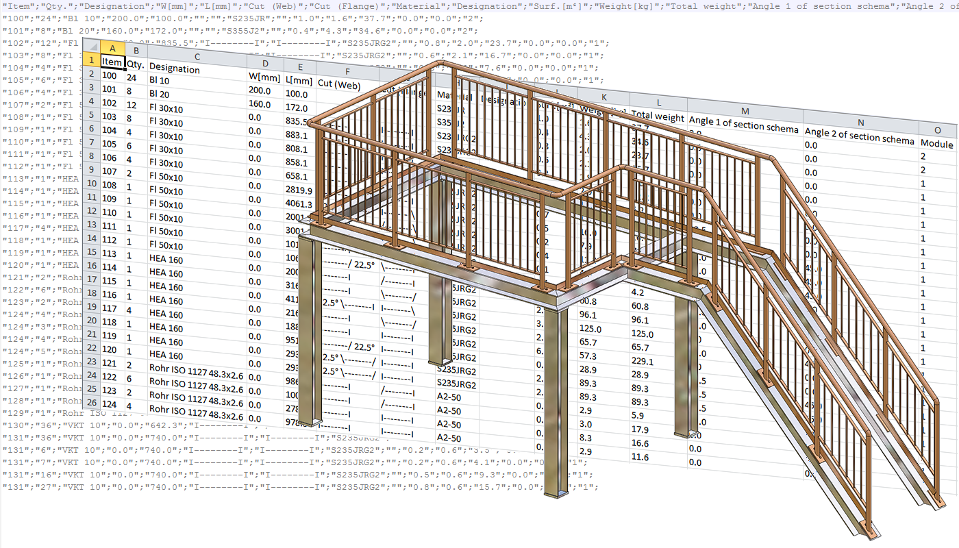
In the Configuration Editor at Steel Engineering, two new parameters for section schemas in BOMs are now available:
Cutting angle reference in section schema
Here you can choose to which leg a specified angle in the section schema is to refer:
Do not show cutting angle in section schema if cut surface
Use this parameter to specify the conditions under which no cutting angle is to be shown in the section schema, since the total length does not correspond to the trimmed length:
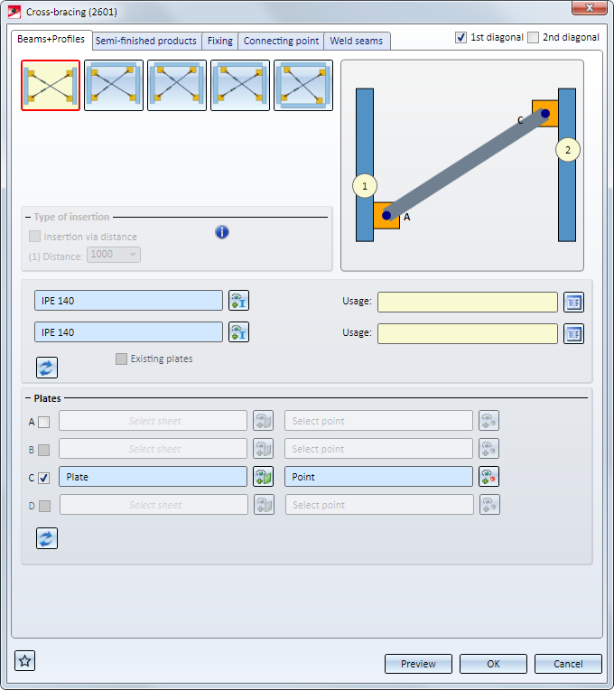
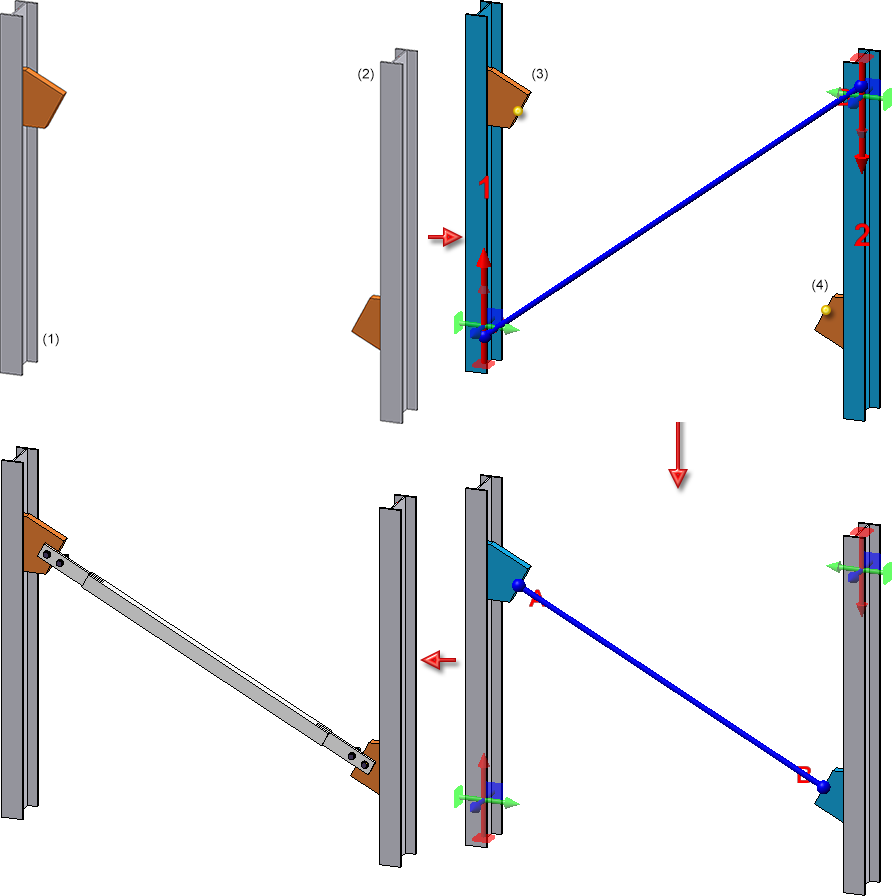
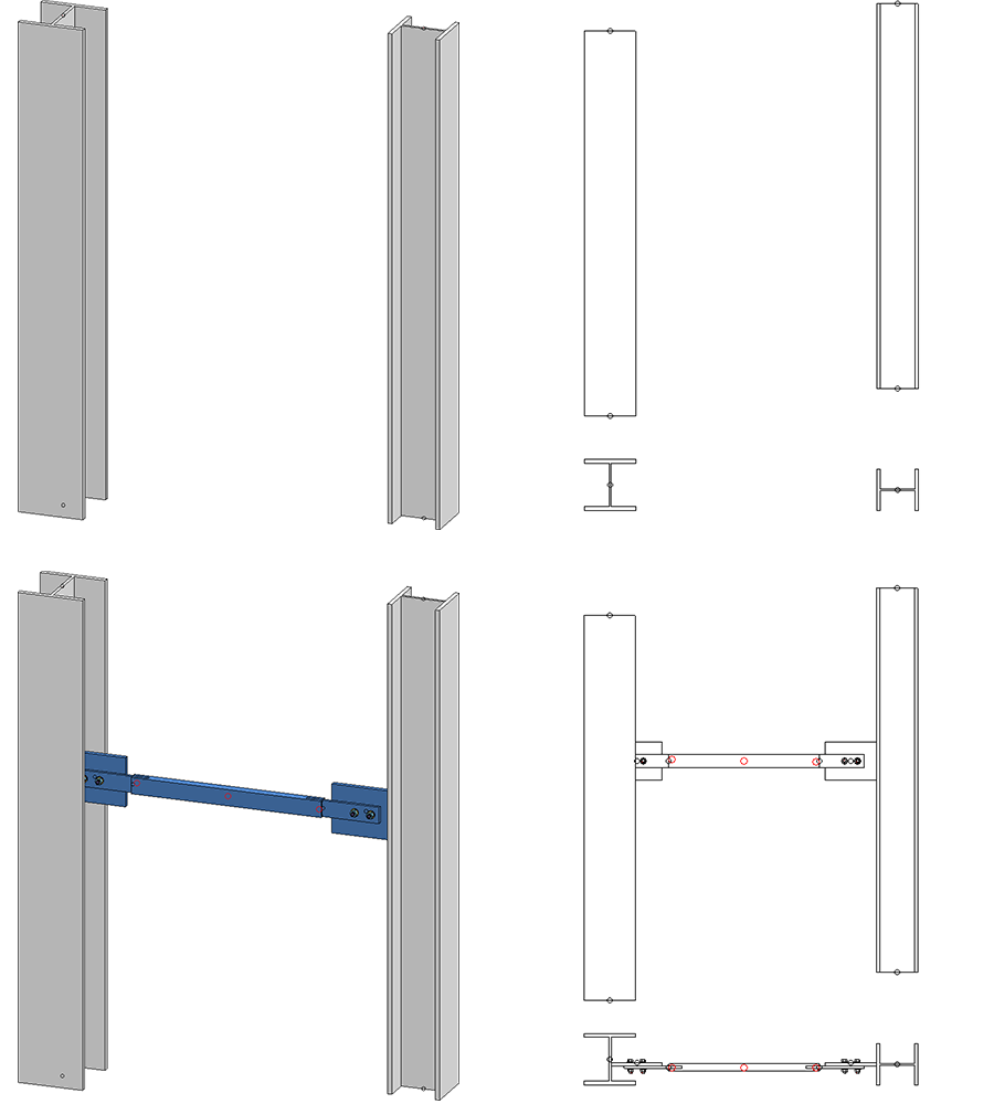
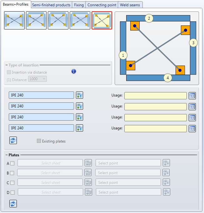
The previous Cross-bracing (1601) has had a redesign (analogous to Cross-bracing (2602)) and has been replaced with the new Cross-bracing (2601). Use this Design Variant to insert cross-bracings as stabilizing elements between 2, 3 or 4 beams or plates.
When connecting profiles, you also have the option to mount the cross-bracing to already existing plates on the beams. This can make sense if, for instance, you want to insert two cross-bracings between 2 beams, and the second cross-bracing is to be mounted to the gusset plates of the first cross-bracing. Also new is the possibility to insert cross-bracings between plates (without assignment to any beams.
On the left hand side you can see a cross-bracing inserted between two beams. The gusset plates here were created together with the connection. Then, as you can see on the right hand side, another cross-bracing was inserted between the beams, mounted to the right gusset plate of the first cross-bracing (C).
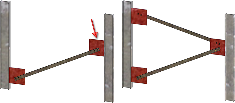
The Usage attribute of the resulting assembly will be automatically initialized with Cross-bracing.
On the Weld seams tab of the Base plate + Anchor plate (2101) dialogue window you can now choose the weld seam type for welded on plates. The tab has been expanded accordingly for this purpose.
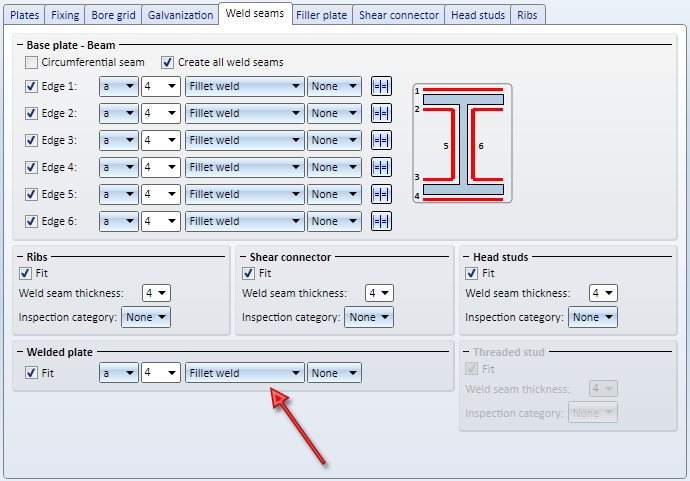
In previous versions,only plates could be selected as connecting plates. FromHiCAD 2019 SP2 onwards it is also possible to generate flat steels and wide steels.
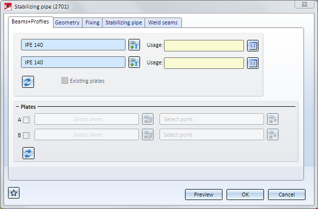
In the image below the two beams (1) und (2) were identified first. Then, in the dialogue window beneath Plates, checkbox A was activated. The gusset plate (3) on the first beam has been chosen as the plate and, as point, the mid point of the gusset plate edge. Next, it was proceeded likewise for Sheet B (4).
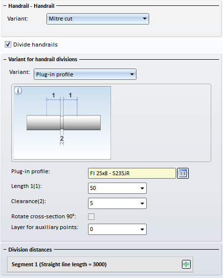
From SP2 onwards, handrails can be divided, e.g. in order to insert plug-in profiles or flat steel joints in long railings. For this purpose, an additional checkbox has been added on the Handrail-Handrail tab.
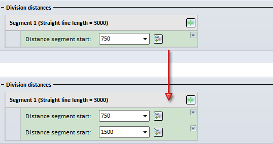
If the checkbox is active, the variant for handrail division and the division of the handrail can be specified by segments.
The divisions can be defined either by specifying the distance from the segment start, or by specifying a division point.
|
|
New division Click on this symbol to add a new division, e.g.:
Enter the distance of the division from the segment start in the input field. |
|
|
New division at selected point Click on this symbol do define the division by specifying a division point. |
Divisions can be deleted at any time by clicking on the  symbol at the top right next to a division.
The following variants for handrail division have been predefined:
The image below shows a railing with divided handrails.
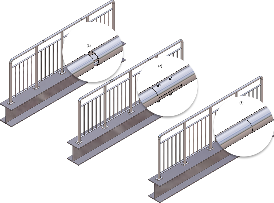
(1) Variant: Plug-in profile, (2) Variant: Flat steel joint, (3) Variant: Straight cut
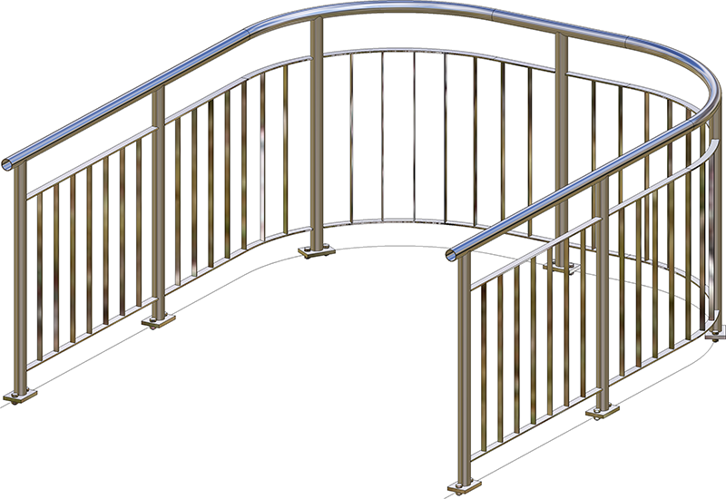
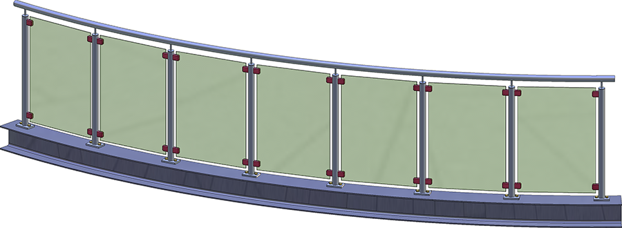
From SP2 onwards, HiCAD allows the creation of curved railings in a plane. This applies to both railings along beams and railings along composite edges. However, this is only possible for curved beams or curved lines of a sketch. Curved beams placed along composite edges are currently not supported yet. The division can be defined either by specifying the distance from the segment start, or by specifying the division point.
Curved railing, created on the basis of arcs
Curved railing, created along a curved beam
The previous functions "Glass" and "Glass along sketch" have been combined into a new function called Laminated glass, which allows the creation of both glass panes in glass fields and the creation of glass panes from sketches.
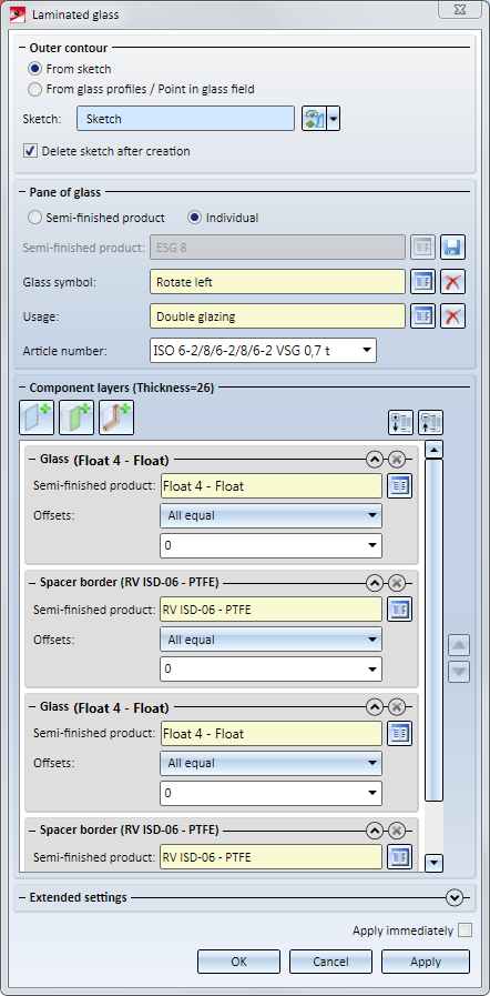
The Laminated glass dialogue window
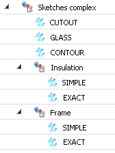
User-defined, sketch-based series beams and profiles consisting of several parts may now be nested arbitrarily in assemblies and dummy parts (exception: CUTOUT, CONTOUR and GLASS) - these must always be contained in the uppermost element.
Nested beam structure and the resulting beam
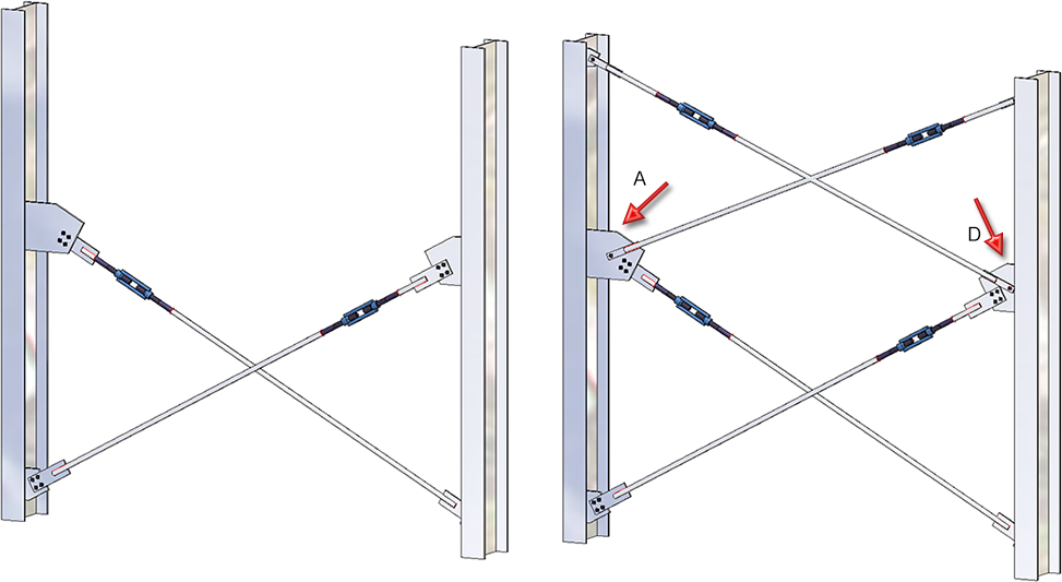
The Cross-bracing (2602) has been further enhanced. In previous versions, the connection automatically supplied the gusset plates. From HiCAD 2019 SP1 onwards you have the option to use already existing plates on the beams as gusset plates. This can be useful in situations where you want to insert two cross-bracings between two beams, and mount the second cross-bracing to the gusset plates of the first cross-bracing.
Also new is the option to insert a cross-bracing between plates (which are not assigned to any beam).
An example:
On the left hand side you see a cross-bracing inserted between two beams. The gusset plates here were created together with the connection. Then, as you can see on the right hand side, another cross-bracing was inserted between the beams, mounted to the gusset plates of the first cross-bracing (A and D).
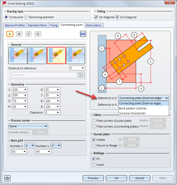
Furthermore, additional options are available for rectangular gusset plates, which influence the position of the connecting plate in relation to the gusset plate.
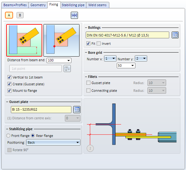
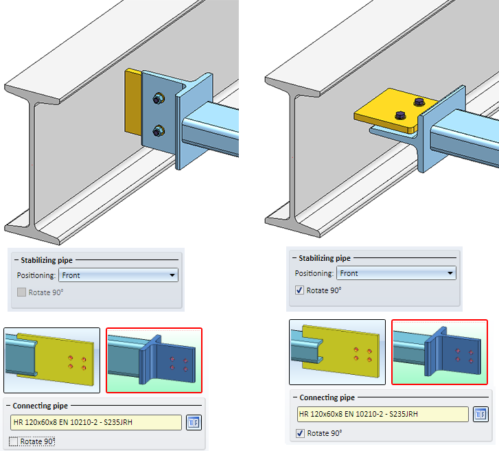
The Fixing tab of the Stabilizing pipe connection has been revised. Beneath Stabilizing pipe you can now determine whether the gusset plate is to be mounted to the front or back of the connecting sheet or T-profile, respectively. Also, you can rotate the connecting plate and T-profile 90° by activating the corresponding checkbox.
The image below shows a stabilizing pipe connection inserted perpendicular to the beam without (left) and with(right) 90° rotation of the gusset plate, the T-profile and the pipe.
For all posts you can now specify a lateral offset to the handrail. For this purpose a new checkbox has been added on the Post tab.
Please note that specifying an offset currently only makes sense if Variant: Console has been selected on the Post-Handrail tab.
Example:
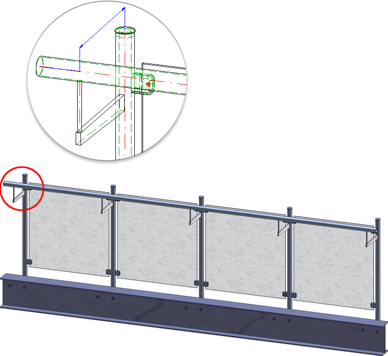
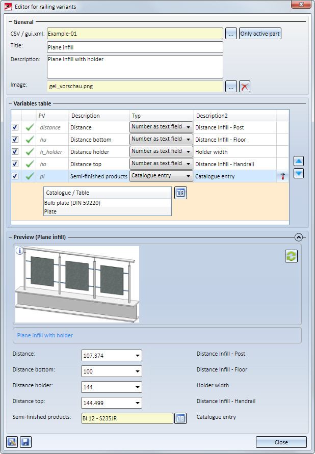
Railing components such as posts, handrails, transition infills, corner infills or the Post-Handrail connection can now also be saved as customer-specific variants. These variants will then be available in the Railing Configurator, allowing an individual composition of railings.
The creation of such variants requires the following steps:
If you have selected the default template Steel/Metal Engineering in the HiCAD Parameter Configuration (ParKonfigComp.exe) in previous versions, the tracking of catalogue changes was automatically switched on in the Configuration Editor at System settings > catalogue. From HiCAD 2019 SP1 onwards, the tracking will be switched off by default.
In the Configuration Editor at Steel Engineering you can specify a Default material for Steel Engineering parts.
In previous versions, the ID of the required table of the Material catalogue and the ID ofthe data record needed to be specified. From HiCAD 2019 SP1 onwards, the selection can be achieved much easier: Simply click on the  symbol and choose the desired material from the Materials or User-defined materials catalogue.

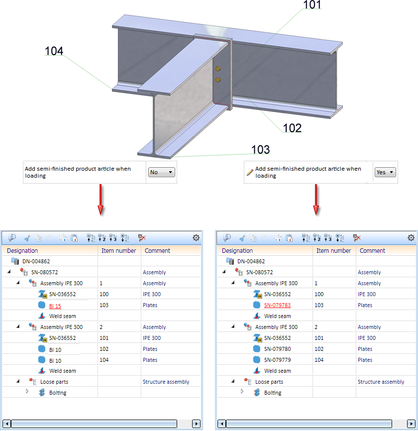
In previous versions, existing article masters of semi-finished products were not transferred to HiCAD when inserting attached parts such as Steel Engineering connections, stairs, railings, element installations, profile installations etc.
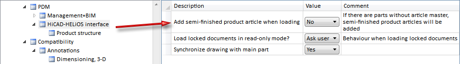
From HiCAD 2019 onwards this behaviour can be changed via a setting in the Configuration Editor: At PDM > HiCAD-HELiOS Interface you can find the parameter Add semi-finished product article when loading. The ISD default setting is No, i.e. the article master of semi-finished products will not be transferred.
For example, when transferring article masters of semi-finished products from user-defined catalogues, set the parameter to Yes.
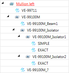
Example:
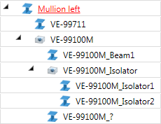
In this example a new model drawing was created and entered into the database. Then, two IPE-beams were inserted and mounted together using the Beam to web, with 2 plates and stiffener (1211) connection. The plates Bl 15 and Bl 10 were chosen from the semi-finished products catalogue, and also have an article master in the HELiOS database. The image below shows, by means of the ICN structure, the difference between the different settings in the Configuration Editor:
The Calculation tab of the Staircase Configurator is now much more intuitive. The different types of stair starts and ends can now be chosen via symbols. The info graphic of the staircase in the dialogue window will be automatically adjusted in the process.
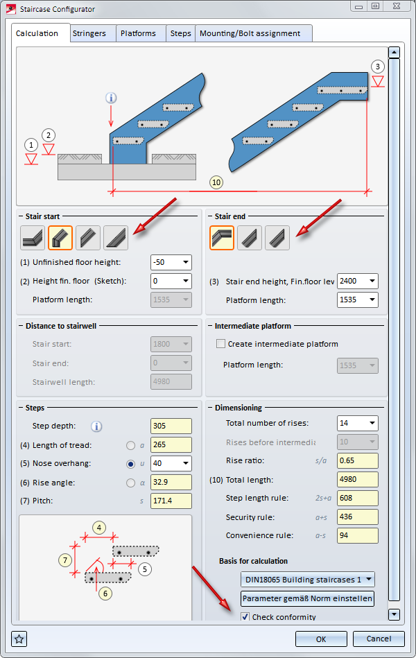
Also new is the Check standard conformity checkbox. If it is active, HiCAD will check on the basis of the specified parameters whether the staircase can be constructed, taking the calculation rules into consideration. If this is not the case, the  symbol will be displayed at the OK button. If you move the cursor over the symbol, the tab and the input fields containing incorrect values will be marked with the
  symbol. Move your cursor onto this symbol to obtain further information and correct the staircase parameter. You can also click on the Set parameters according to standard button to correct the wrong values automatically.
Concrete stairs can no longer be inserted as sub-parts. The corresponding checkbox has been removed from the dialogue window.
If you choose a rectangular plate as gusset plate on the Fixing tab of the Cross-bracing (2602) dialogue window, various selection options on the Connecting point tab will be available to you, allowing you to influence the position of the connection on the gusset plate.
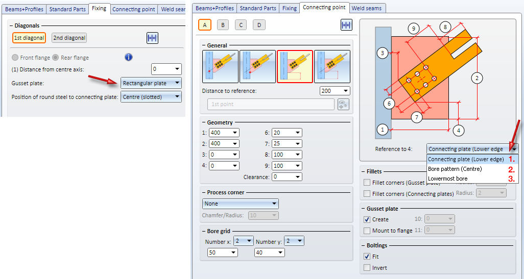
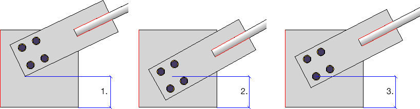
This enables you to determine the centre of the connecting sheet and place the bore in the middle of the gusset plate more easily.
The UNDO behaviour of all Steel Engineering connections has been stabilized and standardized. If a connection is inserted multiple times, i.e. without exiting the function, one UNDO step will refer to the last inserted connection, i.e. the insertion of one connection will be regarded as one step.
From HiCAD 2019 onwards beams created along composite edges can be exchanged.
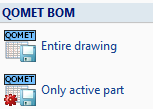
HiCAD 2019 supports the output of QOMET-specific BOMs. QOMET is an ERP system, designed specifically for use in Steel and Metal Engineering.
The BOMs can be output for the entire drawing or for the active part and contain particular columns of the Excel BOM for Steel Engineering (hicad_Stahlbau.xlsc ), which are specifically relevant for QOMET systems. Output takes place in the CSV format.
You find the functions for output of these BOMs at Drawing > Save/Print > Save as  > ....
When carrying out DXF exports via Sheet Metal > Sheet development > Export > Sheets  glass panes will also be considered for export as of HiCAD 2019. If there are multi-layered glass panes, the individual glass layers will be exported.
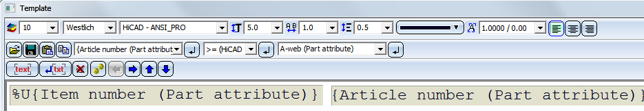
For annotation purposes and file name composition the attributes of the total glass pane can be used. In this context, please observe the information given in the Attributes of superordinate parts paragraph of the Attributes in annotation tags topic.
For instance, if you want the name of the DXF file to be composed of the item number of the complete pane and the article number of the glass pane, this can be achieved in the manual settings for the file name by using the following text blocks:
User-defined series can now not only be created from 2-D parts, but also from 3-D parts that contain assemblies and sketches.

|
© Copyright 1994-2019, ISD Software und Systeme GmbH |