 > Change route
 > Change route
With this function the route of an already installed pipeline can be changed. All segments of the pipeline whose length is still changeable will be taken into account. These are essentially straight pipes, straight segments of bent pipes and guidelines. This means that guidelines and parts are treated equally. No parts will be deleted.
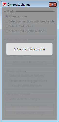
Select point to be moved
After clicking on the function HiCAD will prompt you to select the point that is to be moved.
When moving the cursor over the drawing's pipeline all eligible points of the respective pipeline will be highlighted (Special colour Marking 1). Select the desired point. In the drawing this point (Special colour Marking 3) together with the respective pipeline will be highlighted:
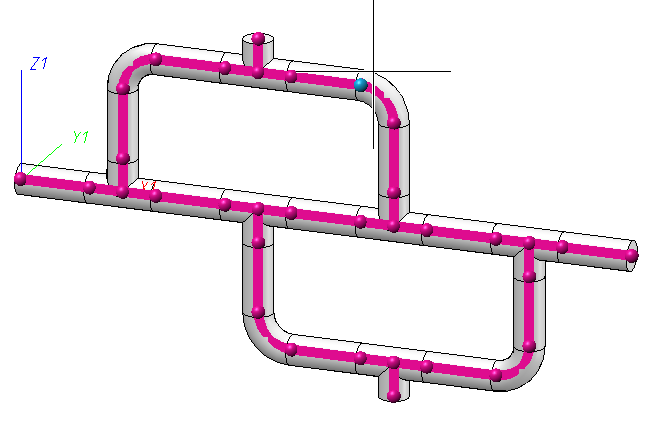
Left-click to adapt this point. HiCAD will ask you to specify the target point of the changed route.
Select target point
When HiCAD requests a target point the display of the pipeline changes: It will have a line representation which shows the route of the pipeline. The lines will be highlighted in different colours:
Line sections that have already reached the maximum length can only be changed if the Observe maximum length checkbox in the dialogue window has been deactivated.
Apart from the line representation two points will be coloured. The light point (Special Colour Marking 2) is the point that you have selected to be moved. The dark point is the so-called fixed point. Fixed points are points whose spatial position is unchangeable. After selecting the point that will be moved HiCAD suggests a fixed point automatically. An explanation on how to change and add fixed points can be found in the Fixed Points section.
If you are satisfied with the current cursor position press the middle mouse button. The changed route will be processed.
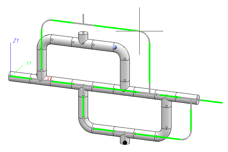
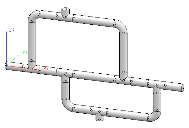
 In the example above the function was exited by pressing the middle mouse button and the selected target point for the changed route was a point in space. More specifically, the point was chosen which is the point closest to the viewing direction of the cursor with the least changes made to the pipeline route. In general, however, the target point will be a point already existent in the drawing, e.g. a connecting point of another pipeline or a vessel's nozzle. Read more about it in the Selection of Target Point section.
While HiCAD requests the target point, you can right-click to open a dialogue window with further options. The availability of options depends on whether you selected a pipeline end point (1) or a point in the middle of the pipeline (2) as the point to be moved.
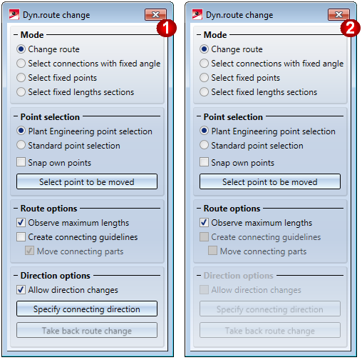
(1) Rohrleitungsendpunkt, (2) Punkt in der Mitte der Rohrleitung
|
Option |
E* |
M* |
|
|---|---|---|---|
|
Plant Engineering point selection |
|
|
If this option is active, only Plant Engineering points will be selectable. This is the default setting. see Selection of Target Point topic |
|
Standard point selection
|
|
|
If this option is active, any other points can be selected. see Selection of Target Point topic |
|
Snap own points |
|
|
By default, the points of a pipeline the route of which has just been changed will not offered as target points. But if you want this, activate the Snap own points checkbox. see Selection of Target Point topic |
|
Select point to be moved |
|
|
Click this button to re-select the point to be moved. The dialogue will change its initial appearance again. This function is helpful in cases where the selection of the correct point is difficult, e.g. if the pipeline ends in narrow parts such as seals and several points are very close to each other. |
|
Observe maximum lengths |
|
|
The Change route function knows maximum and minimum lengths for the expansible segments of a pipeline. To do so it reads the minimum and maximum pipeline lengths from the Plant Engineering settings. Optionally the maximum length can be ignored. For this to happen, deactivate the Observe maximum lengths checkbox. see Maximum/Minimum Lengths topic |
|
Create connecting guidelines |
|
— |
It can happen that the straight segments of a pipeline are not sufficient for shifting the point that is to be moved to the target point. In these cases a connecting guideline can be used. For this to happen, the checkbox needs to be activated. see Connecting Guideline topic |
|
Move connecting parts |
|
— |
If connecting guidelines are created it makes sense to move parts like seals or flanges to the end of the newly created guideline. This behaviour can be changed here. see Move Connecting Parts topic |
|
Allow direction changes |
|
— |
By default, the connecting direction of Plant Engineering connecting points are used in such a way that the orientation of the pipeline can be changed. If you deactivate the Allow direction changes checkbox, no direction changes will be possible any more. see Change Angles topic |
|
Specify connecting direction |
|
— |
The connecting direction cannot just be changed at Plant Engineering connecting points. The Specify connecting direction allows you to pick an arbitrary direction in the drawing. You use the function of a context menu (right-click) for direction specification. see Change Angles topic |
|
Undo direction changes |
|
— |
If you select this option, all directions will be reset to the state of the original pipelines, i.e. all specified direction changes will be undone. see Change Angles topic |
|
Change route |
|
|
By activating this option you switch back into the Change route mode, e.g. after specifying fixed points, connections with fixed angles etc. |
|
Select connections with fixed angle |
|
|
Use this option to select connections for which no direction changes should be allowed. The procedure is the same as the one for selection of fixed points. A single click on a connection marks the connection, another click removes the marking. see Change Angles topic |
|
Select fixed points |
|
|
Via this option you can switch to the fixed point selection. Fixed points are points on a pipeline whose spatial position is unchangeable. see Fixed Points topic |
|
Select fixed lengths sections |
|
|
Alternative to fixed points whole segments can be marked as unchangeable. see Fixed Lengths Sections topic |
* E = Pipeline end point, M=Points in the middle of a pipeline
Clicking  closes the function without changing the route. Alternatively, you can press the ESC key.
 Please note:
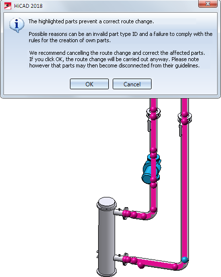
If you click OK you can still carry out the route change - However, we recommend cancelling the route change and correct the highlighted parts instead.
Please also read the information on the special cases Inserted Pipe Lengths. and Pipeline Sets.

Pipeline Tools (PE) • Plant Engineering functions
|
© Copyright 1994-2018, ISD Software und Systeme GmbH |