 > Change route
 > Change route
In order to determine the target point of a changed route a random point in space can be selected. If for example the cursor position is chosen the target point is the point closest to the viewing direction of the cursor with the least changes made to the pipeline route.
In general, however, the target point will be a point already existent in the drawing, e.g. a connecting point of another pipeline or a vessel's nozzle.
Connecting points like that will be highlighted as possible target points as soon as the cursor is moved closer to the target pipeline or the target vessel.
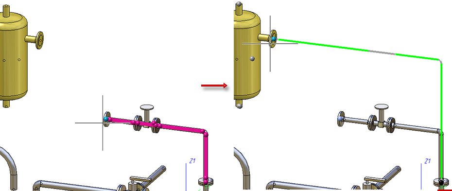
If you now press the middle mouse button the pipeline route will be adjusted:
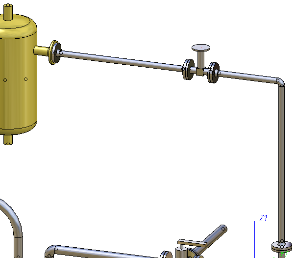
Please not the that confirming the target point by left-clicking only works if the target point has been highlighted. This prevents the unintentional placing of the cursor somewhere in space. However, by pressing the middle mouse button the target point can be placed freely.
Points on the pipeline whose route has just been changed will not be suggested by default. If this is desired please activate the Snap own points checkbox in the dialogue window (right-click to open). If you want to go back to the default settings, deactivate the Snap own points checkbox in the dialogue window.
In the following example the Snap own points checkbox is used to shorten the pipeline to the valve's endpoint.
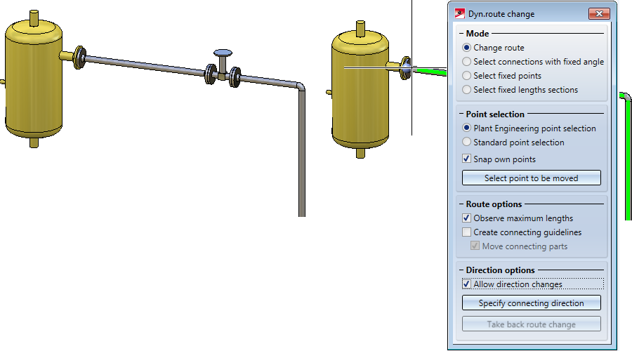
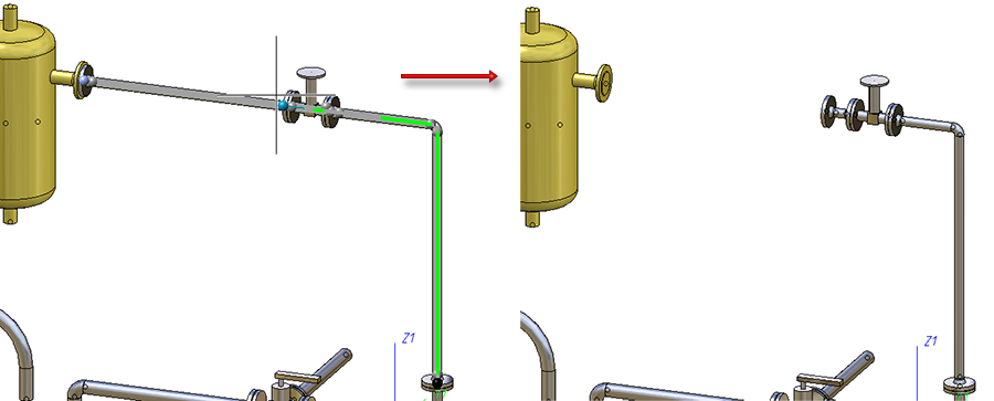
Often, the target point is neither on the pipeline nor on a vessel. The latter is frequently treated as an assembly without transforming it to a Plant Engineering vessel. In this case you can draw on the general HiCAD point options instead of the Plant Engineering point selection. The switch can be made by activating the Standard point selection checkbox in the dialogue window. The following example shows the procedure:
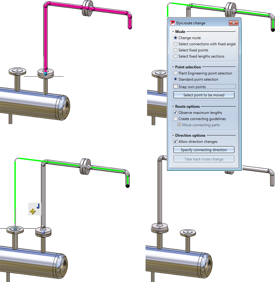
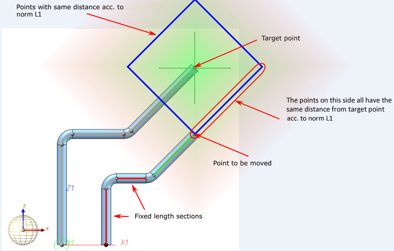
When changing pipeline routes, the minimum distance calculation takes place in accordance with the L1 norm. The effect of this is that, starting from the target point, the directions running parallel to the coordinate axes will be preferred if the target point itself cannot be reached. As of HiCAD 2018 SP1, the local coordinate system will be considered for the calculation.
The effect of the coordinate system on distance calculation can be explained by means of the following example:
Let us assume that you want to perform the change shown below.
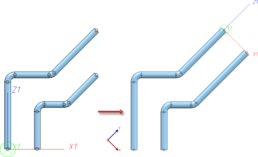
To do this, fix the horizontal and the vertical sections and move the graphic cursor to the target point. If you try to change the route in the World CS in this way, you will realize that this will not work. The reason for this is the above mentioned distance calculation.
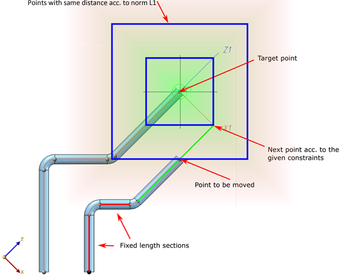
But if you switch to a different coordinate system, e.g. with the function Plant Engineering > Settings > Settings >  > Z points outwards
 , the change will be successful. In the image below the function has been applied to the end point of the left pipeline.

Pipeline Tools (PE) • Plant Engineering functions
|
© Copyright 1994-2018, ISD Software und Systeme GmbH |