Element Installation - What's New?

Service Pack 2 2023 (V 2802)
Feature - Enhanced Create new function
When editing an element installation, no complete recalculation is performed, but only the installation elements selected for editing are handled. If, for example, you have edited parts of an installation element with functions outside the element installation, e.g. moved, deleted or drilled, and this installation element is not changed by selecting another variant or changing the parameters, then these parts remain moved, deleted, drilled, etc.
This behaviour can be changed afterwards with the function Create new in the context menu of the feature Element installation. Previously, dimensions and other edits, e.g. drilling, to parts of the installation elements were lost. As of SP2, these are retained.
The same applies to sub-structures.
You can find an example here.
Major Release 2023 (V 2800)
ALUCOBOND® SZ 20 tray panel (with accessories)
New tab
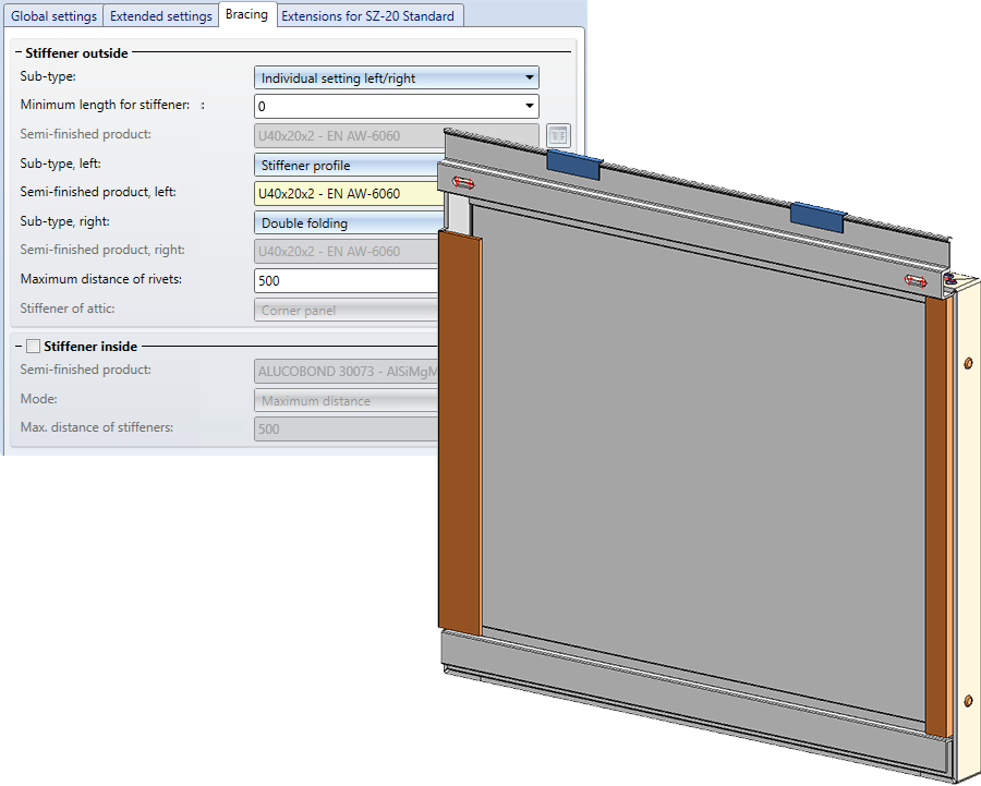
When installing ALUCOBOND® SZ 20 tray panels (with accessories), the settings for stiffener profiles are now available on a separate Bracing tab.
Bracing - Individual setting left/right
For the stiffeners, the settings for the left and right sides can be defined separately. To do this, select the new Individual setting left/right option for Sub-type.
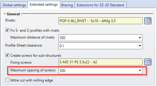
Maximum spacing of screws for sub-structure
For ALUCOBOND® SZ 20 tray panels, the maximum spacing of the screws for the sub-structure can now be defined. The Extended settings tab has been adapted for this purpose.
ALUCOBOND® SZ 20 Polygon (3-8) - Stiffener profiles
When installing panels of type ALUCOBOND® SZ 20 Polygon (3-8), further options are available for the edge configuration:
- Stiffener profile
Stiffener profiles are always riveted to the sheet. You define the profile type and the maximum distance of the rivets on the Extended settings tab. - Double folding
Instead of inserting stiffener profiles on the edge, the material can also be double folded.
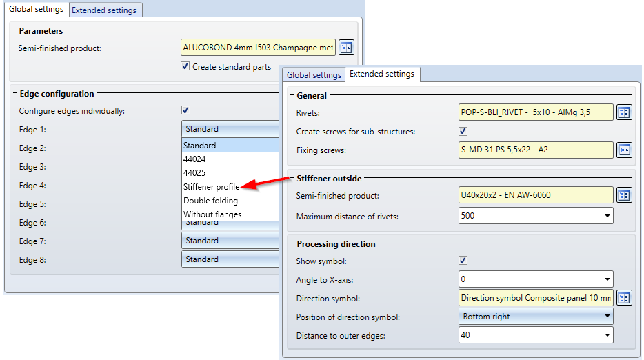
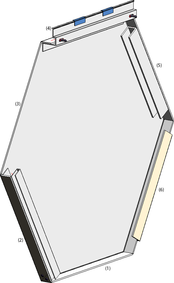
(1) Standard, (2) 44024, (3) Without flanges, (4) 44025, (5) Stiffener profile, (6) Double folding
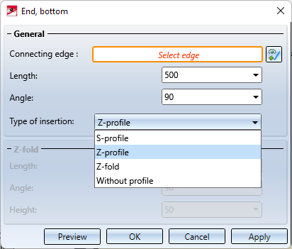
Design variants - SZ20 Base point with projection
The dialogue window now has a Preview button, so that the result can be visualised and checked graphically on the basis of the current entries before applying any changes.
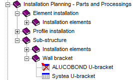
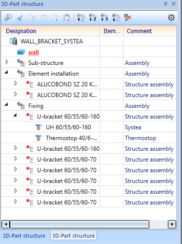
Revised Wall bracket ALUCOBOND U
The ALUCOBOND U-bracket table has been replaced by the Systea U-bracket table. These wall brackets consist of two parts:
- Wall consoles (Systea )
- Thermostop (Systea )
As an example, the following brackets are provided:
- Fixed point:
- UH 60/55/60-160
- Thermostop 40/6-160 mm
- Sliding point :
- UH 60/55/60-70
- Thermostop 40/5-85 mm
The following image shows a wall with an ALUCOBOND SZ20 element installation with an attic and a sub-structure. The wall brackets have been installed with the settings shown.
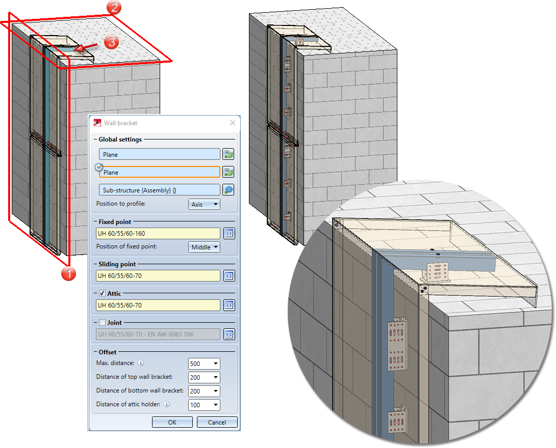
Left: (1) Wall plane, (2) Roof plane, (3) Sub-structure/ Right: Result
The wall brackets are installed as a structure assembly and combined in an assembly called Fixing.
ALUCOBOND © easy fiX
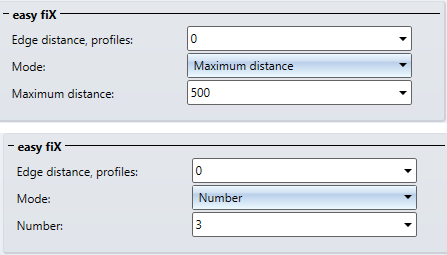
When installing ALUCOBOND easy fiX profiles, you now have the option of selecting a Mode for their insertion:
- Maximum distance
In this mode, the number of profiles created is calculated using the value specified here.
- Number
If this mode is selected, the value specified here determines how many profiles will be created. This value only applies to profiles that are not continuous.