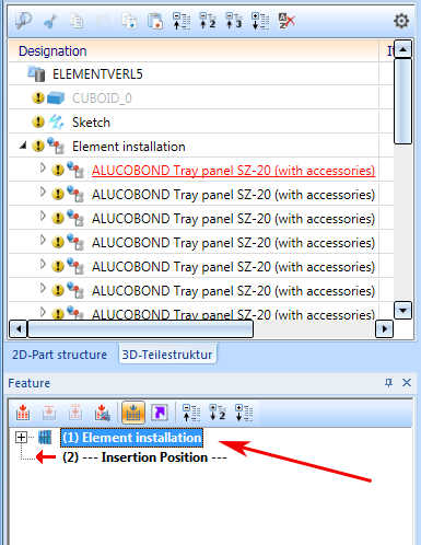
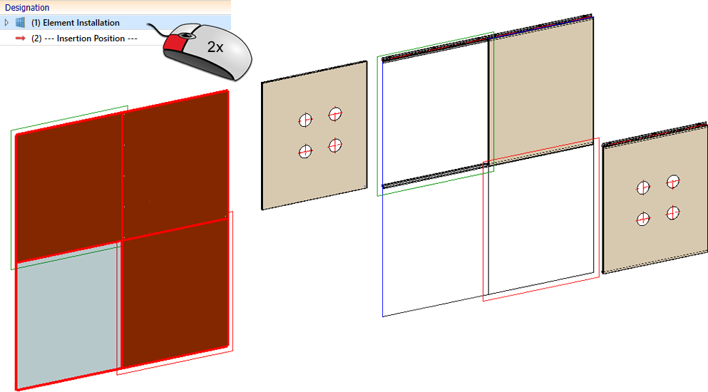
To edit installed elements, double-click the corresponding feature entry of the Element installation assembly. You can then change or delete installation elements, or add new ones.
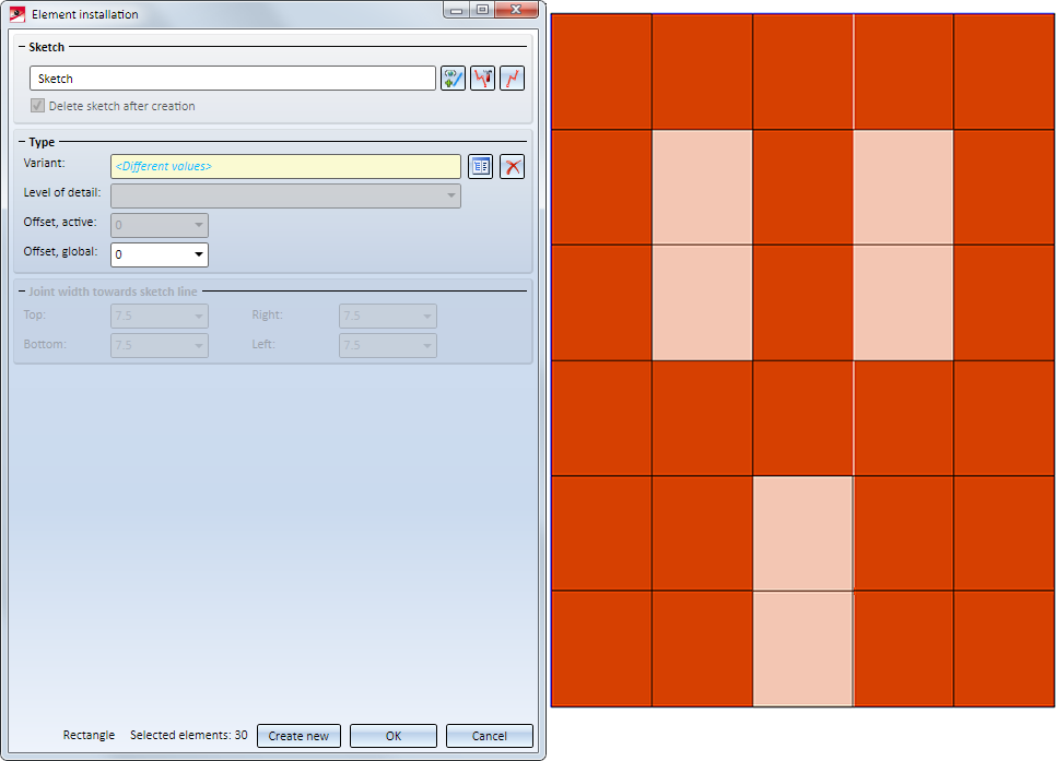
The Element installation dialogue window ill then be displayed. In the model drawing the still empty areas of the installation sketch, i.e. the areas where elements can still be placed, are shown in light orange. The dark orange areas are already occupied.
When installing elements - especially for complex facades - it is often the case in practice that certain installation elements have the same options. To make it easier to select the areas to be occupied (rectangular or polygonal sketch areas) and to edit installation elements with the same parameters, HiCAD offers the possibility to work with so-called selection groups. The advantage is that you can group installation elements with the same parameters and then select or deselect all elements of this group with one click. The Selection groups area is available in the Installation elements dialogue window.
Detailed information on working with selection groups can be found here.
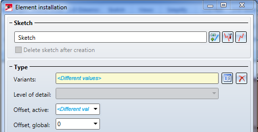
If the same settings apply to all already installed elements, these will be shown in the dialogue window. If the settings differ, the text <Different values> will be shown in the corresponding input field of the dialogue window.
You can select the different editing options without closing the Element installation dialogue window. All changes will only be applied after closing the window with OK or Reset.
Please note the following:
- When you edit the element installation, no complete recalculation will be performed, but only the installation element that you selected for editing will be recalculated. For instance, if you have processed parts of an installation element with functions outside the Element Installation module, e.g. moved, deleted or drilled them, and this installation element is not changed (e.g. through selection of a different variant or parameter changes), these parts will remain moved, deleted or drilled.
- If a variant has been used for the first time in an element installation, - whether during its creation or subsequent editing - it will be "frozen" for this element installation, i.e. in this element installation it will only be used in this state. Moreover, this means that:
- during recalculation of the element installation this state will still be used, even if a newer state of the variant exists in the catalogue.
- if this variant is selected for a previously free or differently occupied sketch area, the "frozen" state will be used as well.
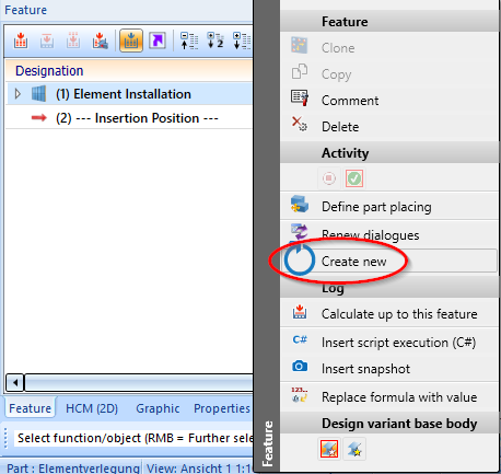
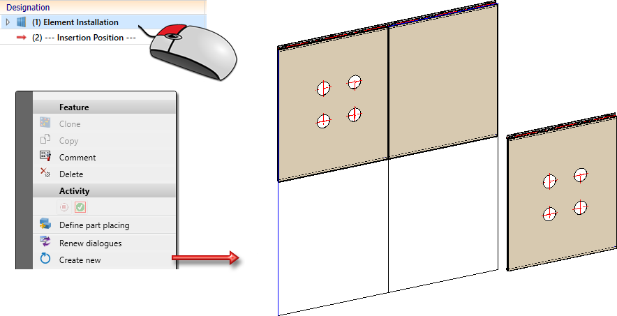
If you do not want this behaviour, click Create new instead of OK. If the dialogue window will be closed by clicking Create new , the following will happen:
The function has the following effect:
- All selected installation elements will be recalculated based on the specified parameters. In the process, deleted or moved parts of the installation elements will be restored.
- "Frozen" variants will be updated, i.e. the variants will be adjusted to current state in the catalogue.
- Dimensions and all additional processings on the parts, e.g. bores, will be preserved.
An example:
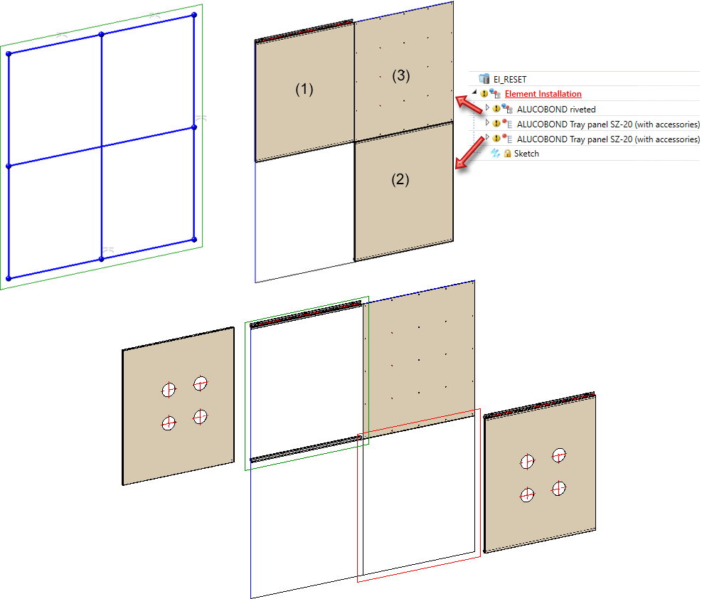
In the following image, the variant ALUCOBOND Tray panel SZ 20 with the default parameters was selected for the fields (1) and (2) of the sketch, and the variant ALUCOBOND riveted for field (3). Then the complete installation element (2) was drilled and moved. For the installation element (1), only the sheet metal was drilled and moved.
Now the processing of the element installation is started via the feature log and the variant ALUCOBOND Tray panel SZ 20 is selected for all three elements - without any further changes to the parameters. This means that nothing has changed for the installation elements (1) and (2) ). If the dialogue window is closed with OK, only the installation element (3) is recalculated.
If the Create new function is then called, all installation elements are recalculated. The plate of installation element (1) is moved back to its original position, the holes remain. Installation element (3) remains in its position together with the bore, since the panel was moved completely.
If installation elements are referenced, the Element installation feature will be deleted. This means that an editing via the Element installation dialogue window will no longer be possible.

Delete installation elements
To delete installation elements, select the elements with the cursor. The selected elements will be highlighted and can then be deleted with a click on the  symbol.
You have the following option to select the elements you want to delete:
- If you want to delete all highlighted installation elements after calling the dialogue window, a click on the will suffice.
-
You can also mark several elements at once: You can
- right-click, choose the Select in rectangle function and, while holding down the left mouse button, draw a rectangle around the elements to be deleted, or
- while holding down the CTRL key and the left mouse button, immediately draw a rectangle around the elements to be deleted, or
- while holding down the CTRL key, identify the elements you want to delete with a left-click.
In the preview the elements will be immediately deleted by clicking the symbols. However, the actual deletion will only take place after confirming with OK.
 Please note:
- When you delete all installation elements, the Element installation assembly will be preserved.
- If you want to delete entire element installation drawing - including the Element installation assembly - you can right-click on the corresponding feature entry and choose Delete.
Add or change installation elements
If you want to place elements on still empty parts of the element installation sketch, or change already existing installation elements, proceed as described in the Element Installation: Basic Procedures topic.
Choose the desired sketch areas and specify the required settings. To select the elements, proceed as described in the Element Installation: Basic Procedures topic.
Example
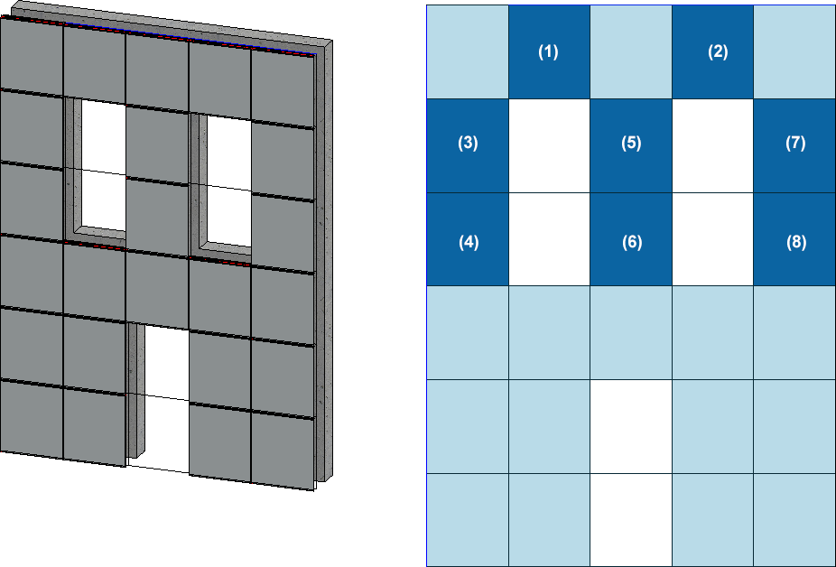
We will use the example from the Element Installation: Basic Procedures topic here. Let us assume that you want to change the installation elements of the dark blue areas (1) - (8): Instead of the standard design you want to use the window connection.
After double-clicking the Element installation feature entry, the following steps must be taken:
Step 1:
- Select the elements (1) and (2) while holding down the CTRL key.
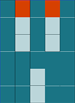
- Change the connection types as shown below:
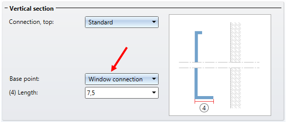
Step 2:
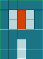
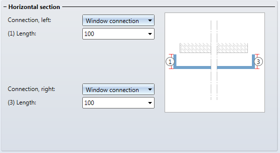
- Select the elements (3) and (4).
- Change the connection types as shown below:
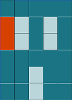
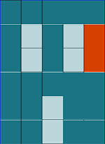
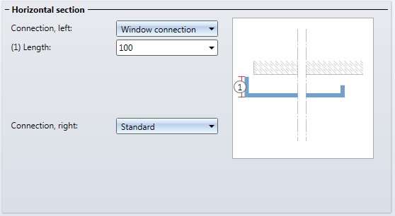
Step 3:
- Select the elements (5) and (6).
- Change the connection types as shown below:
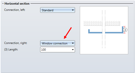
Step 4:
- Select the elements (7) and (8).
- Change the connection types as shown below:
- Confirm your changes with OK.
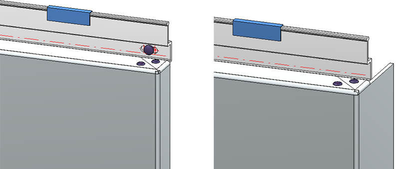
Left: Installation element (3), previously with type "Standard"; Right: Installation element (3) after its change to "Window connection"

Element Installation: Basic Procedures • Marking Colours • Element Installation: Example