You have the option to automatically create wall holders for sub-structures. For this purpose you can find the Wall brackets function in the Civil Engineering functions docking window.
After calling the function the Wall brackets dialogue window will be displayed:
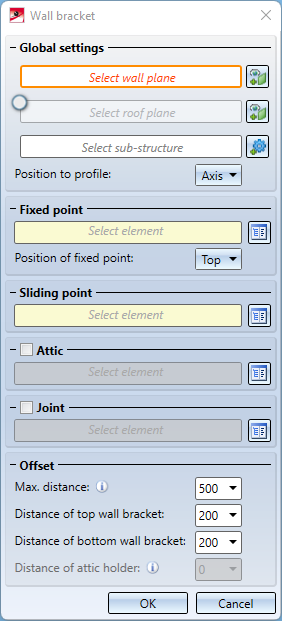
Global settings
Wall brackets are mounted on a wall plane. Select them in the Select wall plane field.
If the sub-structure is with attic, a wall bracket for the attic can also be attached. To do this, you can activate the Select roof plane field and then select the roof plane here. Finally, Select the sub-structure in the field of the same name. Here you have the option of selecting the entire sub-structure assembly in order to provide the entire sub-structure with wall brackets - or alternatively only a single profile of the sub-structure in order to provide only this profile with wall brackets.
The plane selection can also be changed by clicking on the  symbol:
The Position to profile determines the horizontal position of the wall brackets to the profile of the sub-structure (sub-structure profile). You have the following options here:
- Axis
The wall brackets are placed centrally under the profiles of the sub-structure (for U-shaped profiles that are fixed on both sides). - Left / Right
The wall brackets are attached to the left or right of the sub-structure profiles (for L-shaped brackets that are attached to one side of the sub-structure profile).
Fixed point / Sliding point
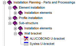
One fixed point and several sliding points are installed per sub-structure profile. You can select one wall bracket each from the catalogue as a Fixed point and a Sliding point. The paths Factory standards\Installation Planning - Parts and Processings\Sub-structure\Wall brackets and Factory standards\Purchased/Factory standard parts\Wall consoles are available for selection. In addition, you can set where the fixed point is to be placed on the profile in Position of fixed point: Top, Middle or Bottom. Please note that with the Middle setting, the fixed point is not placed exactly in the middle of the sub-structure, but only the fastening point closest to the middle is used as the fixed point
Attic / Joint
If you use an Attic, you can activate the item of the same name and additionally select a holder for the attic from the catalogue. In this case, a Roof plane must be selected!
If the sub-structure contains joints, you can have them provided with wall brackets. To do this, activate the Joint option and then select a wall bracket from the catalogue. These wall brackets are then placed centrally on joints and taken into account in the distance calculations. If this option is not activated, each profile of the sub-structure is considered separately and provided with wall brackets.
In the Offset area you can influence the vertical distances of the wall brackets. Distance of top wall bracket and Distance of bottom wall bracket define the exact distance of the top or bottom wall bracket from the top or bottom edge of the wall or sub-structure profile. In between, wall brackets are evenly distributed so that they are no more than the Max. distance apart.
If you are using an Attic and have activated the Attic checkbox, you can also set the Distance of attic holder. This value controls the exact distance of the attic holder from the front edge of the roof.
Example:
The following image shows a wall with an ALUCOBOND SZ20 element installation with an attic and a sub-structure. The wall brackets have been installed with the settings shown.
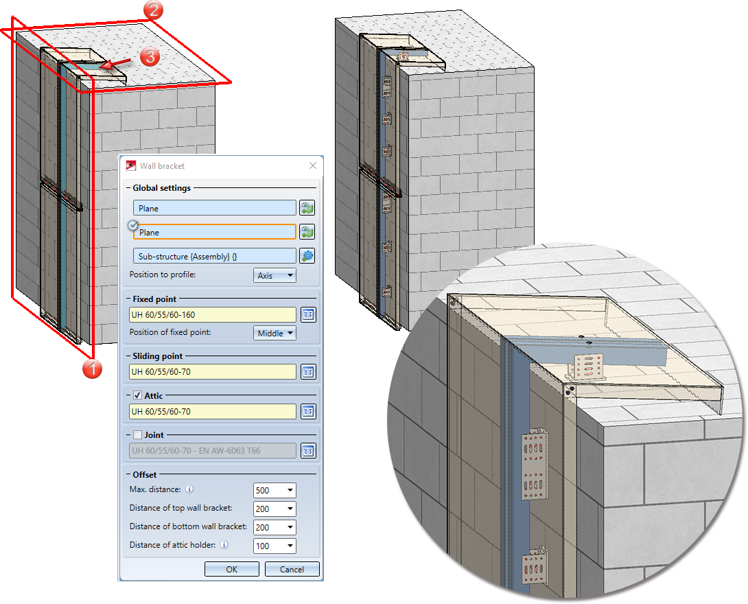
Left: (1) Wall plane, (2) Roof plane, (3) Sub-structure/ Right: Result
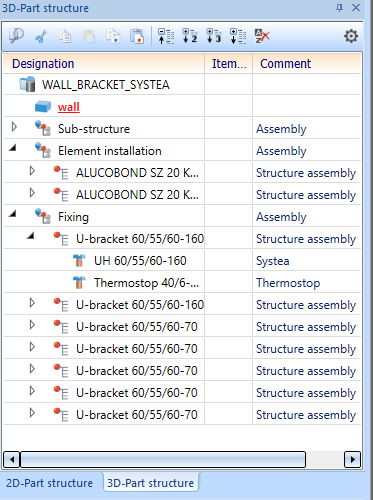
The wall brackets are installed as a structure assembly and combined in an assembly called Fixing.
![]() Please note:
Please note:
In HiCAD 2023 (V 2800) the ALUCOBOND U-bracket table has been replaced by the Systea U-bracket table. These wall brackets consist of two parts:
- Wall consoles (Systea )
- Thermostop (Systea )
As an example, the following brackets are provided:
- Fixed point:
- UH 60/55/60-160
- Thermostop 40/6-160 mm
- Sliding point :
- UH 60/55/60-70
- Thermostop 40/5-85 mm

Create your own wall brackets
Besides using the wall brackets supplied by the ISD, you can also define and insert your own wall brackets.
Wall brackets are normal parts that are saved in the catalogue. They require a Fitting CS which will be placed on the fitting point. The X-axis points crosswise to the profile direction, or, in the case of wall brackets mounted on one side, away from the profile. The Y-axis then points in profile direction.
For creating mounting drawings, a named point "!" will be required, for which the dimensions will be created.
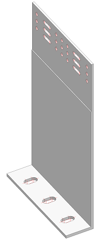
In the present example, a wall bracket for the Purchased/Factory standard parts for a usage of Wall bracket is to be prepared.
Choose 3-D Standard > Standard Parts > BoltScrew  > Purchased/Factory standard parts and insert a wall bracket into a model drawing. In this case, select Wall consoles > Systea > L-Wall consoles > WB2 40/80/3-160.
These parts contain 3 isolated points, which are perfectly suited for defining the Fitting CS. Open the context menu in the still empty Feature log of the wall bracket and choose Switch feature on. Then, select Drawing > Others > World CS > Define Fitting CS. HiCAD will then prompt you to specify the 3 points: Origin, Point in X-direction, Point in Y-direction. Choose the 3 points as shown in the graphic.
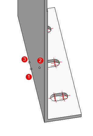
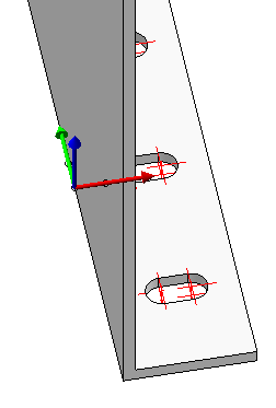
Left: Points for the Fitting CS: (1) Origin, (2) Point in X-direction, (3) Point in Y-direction. Right: Result
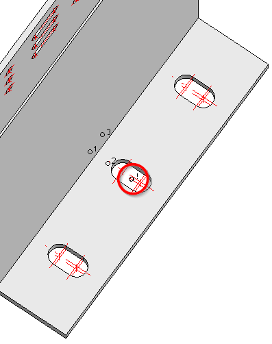
For dimensioning in mounting drawings an additional named point "!" must exist, in relation to which the dimensions will be created. This point can be located in the origin, but also elsewhere. In this case the dimension point should be in the centre of the middle bore.
Choose 3-D Standard > Tools > New point to place an isolated point in the centre of the middle bore. Then, choose 3-D Standard > Tools > Point > New point number, identify the point you have just created and assign the point name "!" to it.
You can then save the finished part to the catalogue: Choose Drawing > Save/Reference > Reference part, Save, Detail drawing. In the dialogue window, select the option Save as part with catalogue entry and save the part to the catalogue beneath Installation planning - Parts and Processings > Sub-structure> Wall bracket.
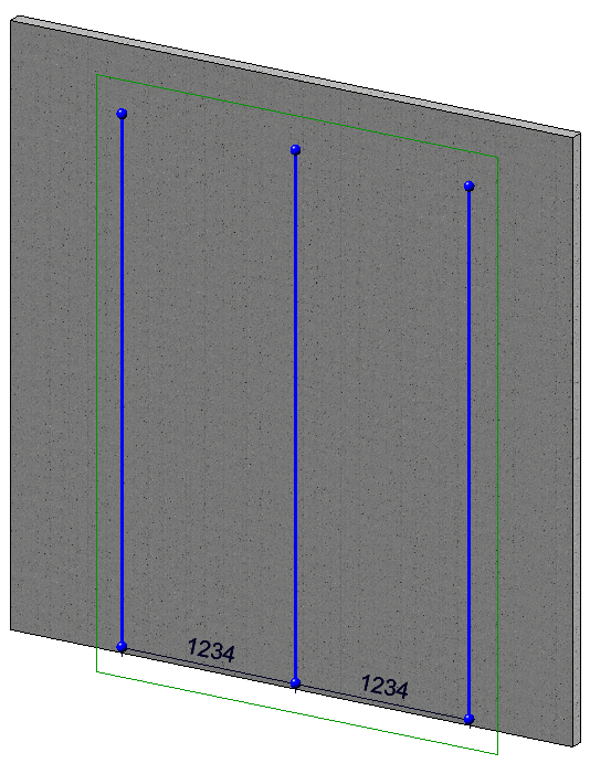
You can now insert the wall brackets. Let's assume that a wall is given. A sketch for a sub-structure is created on this wall:
The function Element installation > Sub-structure in the Civil Engineering functions docking window is called to create a sub-structure based on the sketch. The type of sub-structure selected here is the ALUCOBOND SZ-20 sub-structure. The Offset, global value is set to 150 so that the sub-structure is created with the appropriate distance to the wall for our wall brackets.
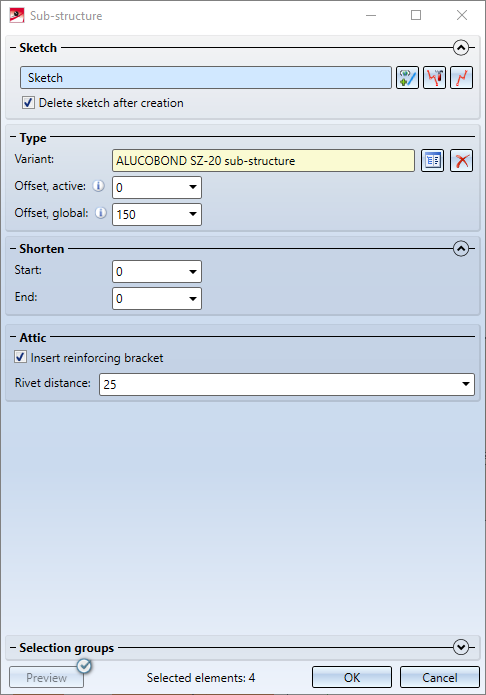
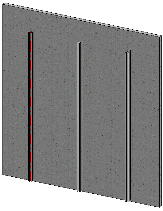
Click OK to create the sub-structure:
In order to insert the wall brackets, use the function Element installation > Wall bracket in the Civil Engineering functions docking window. The front of the wall is selected as the Wall plane, and the sub-structure just created is selected as the sub-structure. The previously created wall bracket is selected as both the Fixed point and the Sliding point.
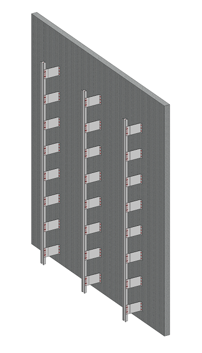
The result: Your own wall brackets on a sub-structure
Restoring the wall brackets
Adjustments made manually to wall brackets, such as moving or deleting individual consoles, are retained even after the wall brackets have been recalculated. In case you want to discard your changes, the context menu of the Wall bracket entry in the feature log provides the function Restore, which discards all adjustments and re-generates all wall brackets.

Create Own Profiles for Sub-structures • Customizing the Dialogue Window