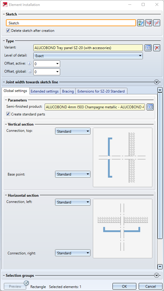
In the dialogue window for the ALUCOBOND Tray panel SZ-20 (with accessories) you can find 3 tabs with setting options:
Further topics:
Please also note the Design Variant Flange for SZ20.

Global settings
Here you can choose the desired semi-fnished product and the parameters for Connection, top, Base point, Connection, left and Connection, right. Furthermore, you can choose here whether standard parts (for fastening) should be installed or not. The ISD default setting is that standard parts are created, i.e. the checkbox is active. If the checkbox is inactive, the standard parts are not listed in the bill of materials.
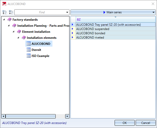
Selection of ALUCOBOND Semi-finished products:
Possible connection options:
|
Horizontal section |
|||
|
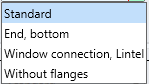
Top |
|
Base point |
|
|
Vertical section |
|||
|
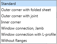
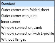
Left |
|
Right |
|
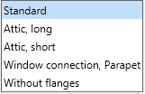
Depending on the chosen connection type, further input fields may be displayed.
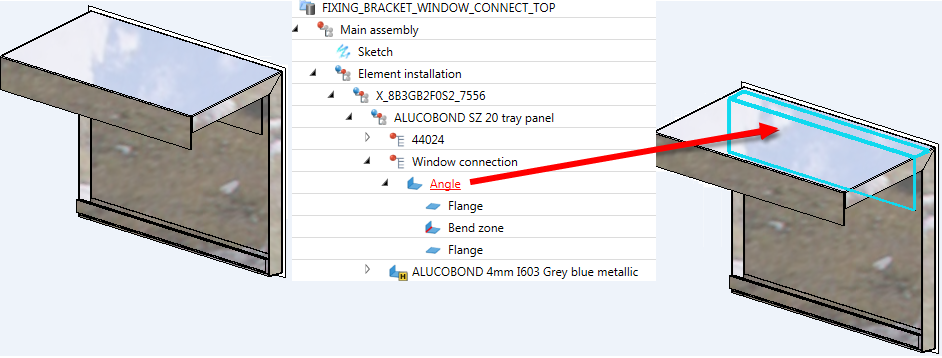
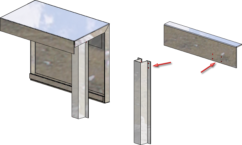
If you choose Connection, top: Window connection, parapet beneath Vertical section when installing ALUCOBOND®Tray panels SZ-20, an additional angular L-bracket will be used for the connection.
If you connect such an element installation with a sub-structure, the sub-structure will be shortened appropriately. Also, bores will be applied to the sub-structure and the fixing brackets.
If Connection top: Window connection has been selected for the vertical section, the connection can also be installed without flanges. To do this, simply enter the value 0 for Length of folded sheet.
The Attic connection can also be installed without the last flange by entering the value 0 for Length of folded sheet.
If you enter a negative value for Length of folded sheet, the folding will be generated in the other direction ("upwards" or "downwards").
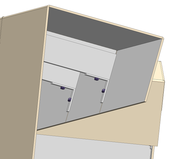
 When installing ALUCOBOND SZ-20 tray panels with window connection, the "L-profile" is no longer part of the panel since HiCAD 2020 SP2. Instead, it is only created by the connection with the sub-structure. It is designed as a "short piece" on each sub-structure and is not continuous.
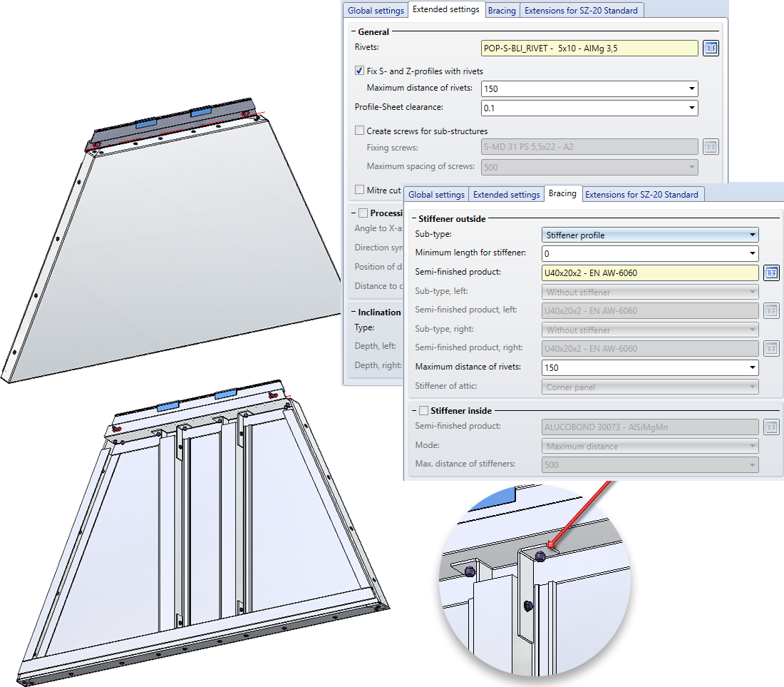
Extended settings
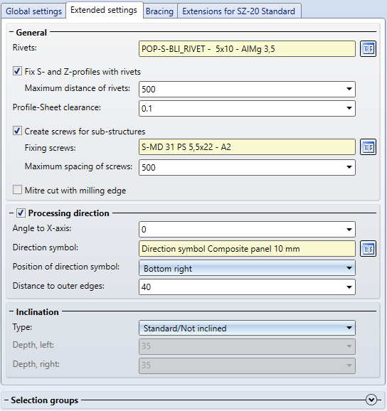
On this tab you define the processings for the suspension profiles.
- Under General you select the rivets and screws for mounting the profiles to the sheet metal panel.
If the S- and Z-profiles (suspension profiles) are to be riveted to the sheet metal panel, activate the Fix S- and Z-profiles with rivets checkbox and define the Maximum distance of the rivets.
By activating the Create screws for sub-structure checkbox, you can determine whether the screws for the sub-structure should be generated. A Maximum spacing of screws can also be specified.
If you want the mitre cut to be displayed in the sheet development with milling edge, activate the Mitre cut with milling edge checkbox.
- By activating the Processing direction checkbox and specifying an angle, you can define grain direction of the sheet metal panels. In addition, you can select the direction symbol and specify the position of the symbol and the distance from the outer edges of the panel.
- If Standard and Without flanges are selected on the Global settings tab, SZ20 cassettes can also be inclined horizontally or vertically.
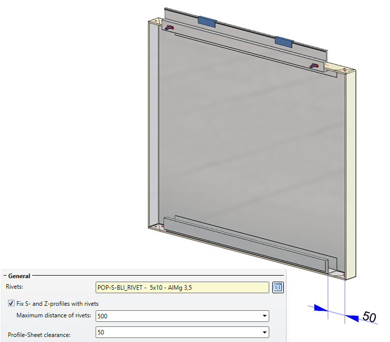
The length of the S- and Z-profiles (suspension profiles) can be influenced by specifying the Profile-Sheet clearance.
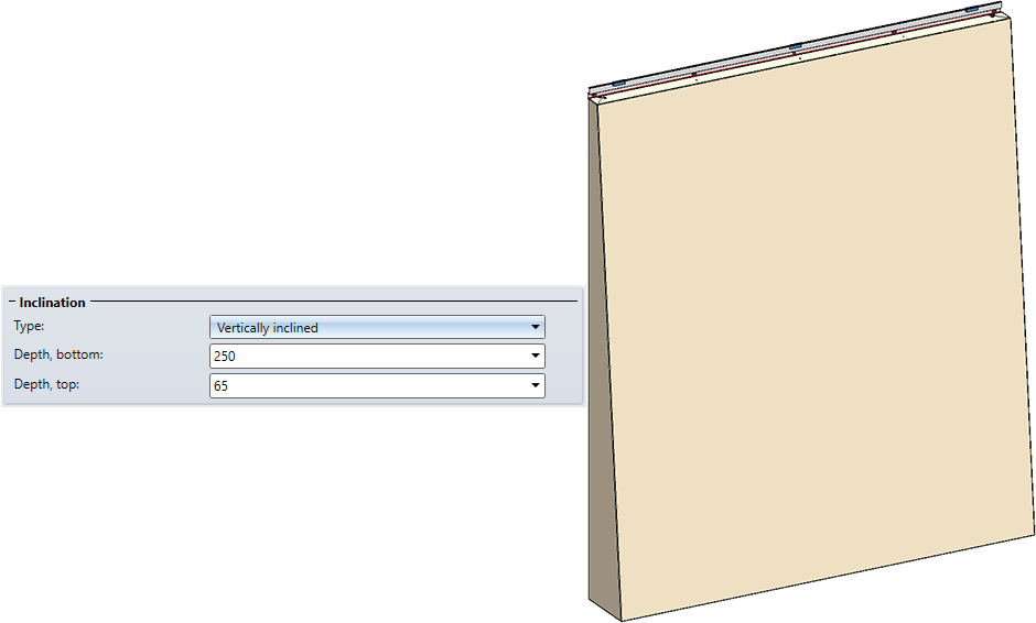
Tray panel with vertical inclination
Bracing
On this tab, you define the processings for the stiffener profiles.
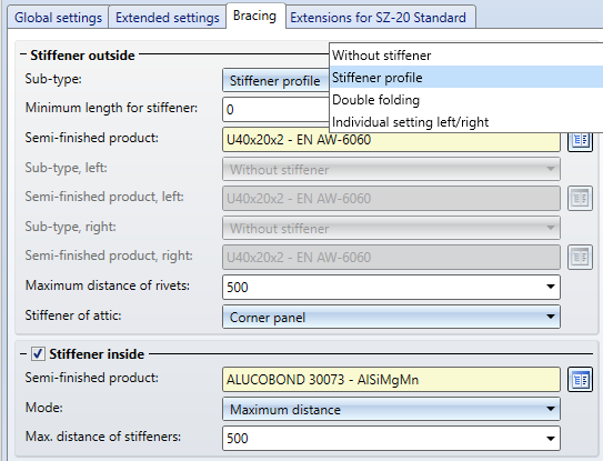
Under Stiffener outside / Stiffener inside you specify which stiffener profiles are to be inserted.
Note that stiffener profiles inside are only possible if the checkbox Fix S- and Z-profiles with rivets is deactivated on the Extended settings tab.
Select the rivets in each case and determine the Maximum distance of rivets or add the desired number of stiffeners. The stiffener profiles within are evenly distributed according to the maximum distance or according to the number of stiffeners.
Stiffener profiles are always riveted to the panel.
Instead of stiffener profiles on the edge, the material can also be double edged. For this purpose, the option Double folding is available in the Sub-type selection list.
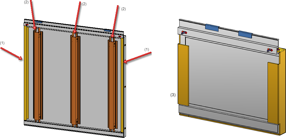
ALUCOBOND® SZ 20 tray panel - (1) Stiffener outside, (2) Stiffener inside, (3) Double folding
It is also possible to select different settings for the left and right side. To do this, select the option Individual setting left/right for Sub-type.
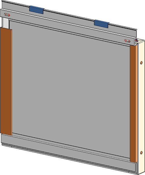
ALUCOBOND® SZ 20 tray panel - Individual setting left/right
For parapet connections, it is possible to extend the Stiffener outside up to the parapet and rivet it to the flanges. To do this, select Side stiffener for Stiffener of attic.
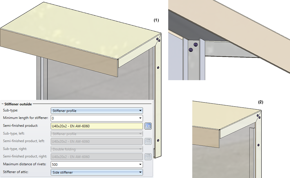
(1) Stiffener lengthened up to attic; (2) Stiffener of attic = Corner panel
Please note the following for ALUCOBOND® SZ 20 tray panels - depending on the settings during insertion:
- The S- and Z-profiles are cut to fit.
- The stiffener profiles are cut on the S- and Z-profiles.
- The stiffener profiles are bonded and fixed at the top and bottom with angle-shaped Sheet Metal parts.
- The holes for these angles are not generated in HiCAD. Reason: They are not generated by the machine, but by the processor after the stiffener profile has been bonded to the sheet metal. This bonding cannot be done so precisely that previously drilled holes would fit. (1)
Example of a trapezoidal ALUCOBOND® SZ 20 tray panel, (1) No holes are created here!
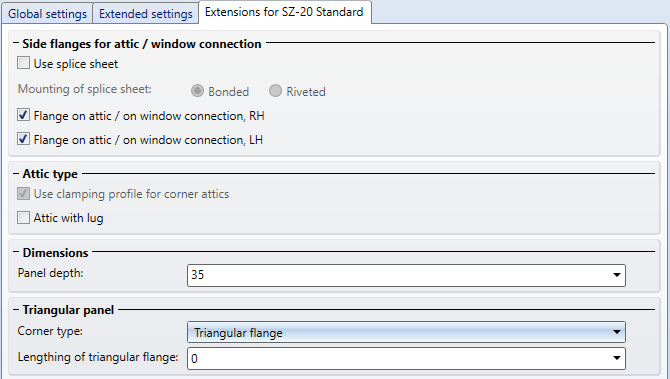
Extensions for SZ-20 Standard
On this tab you can specify the type of the lateral flanges for the connection types Attic, long / Attic, short. Also, you can specify here whether corner attics are to be created with or without clamping profile. Furthermore, you can specify the depth of the tray panel here.
In addition, you can determine the type of the acute corner for triangular panels.
The connection between splice sheet and panel can be a bonded or a riveted one. The rivets will be inserted on one attic side only, at a 50 mm distance to the edge.
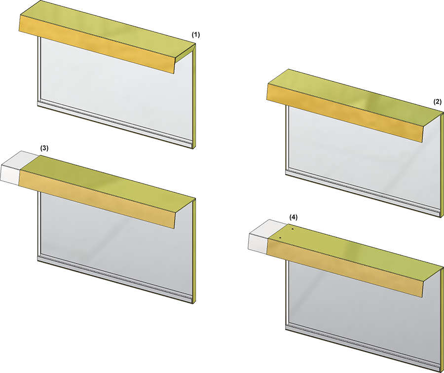
(1) Standard; (2) Without side flanges; (3) Splice sheet, bonded; (4) Splice sheet, riveted
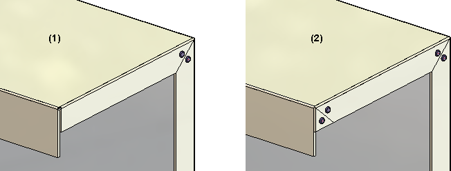
The image below shows a SZ-20 tray panel. Horizontal section: Connection, top. Attic, long; Vertical section: Connection, right. Outer corner with folded sheet. The left tray panel has been created with splice sheet and clamping profile, the right one without these elements.
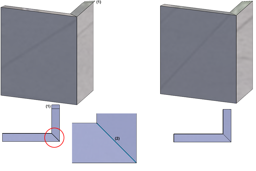
(1) Splice sheet, (2) Corner attic with clamping profile
Attic connections can be created with or without lug:
(1) With lug; (2) Without lug
For triangular panels, you can choose between the Open and Triangular flange versions for the Corner type for the acute corner.
Left: Corner type "Open"; Right: Corner type: "Triangular flange"
If you choose the option Triangular flange, you can also enter a value for the Lengthening of triangular flange, which lengthens the flange accordingly.
Lengthening of triangular flange from the above example by 50mm.
Sub-structures ALUCOBOND SZ 20
For SZ 20 element installations, a matching profile for a sub-structure is available.
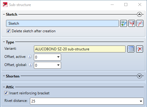
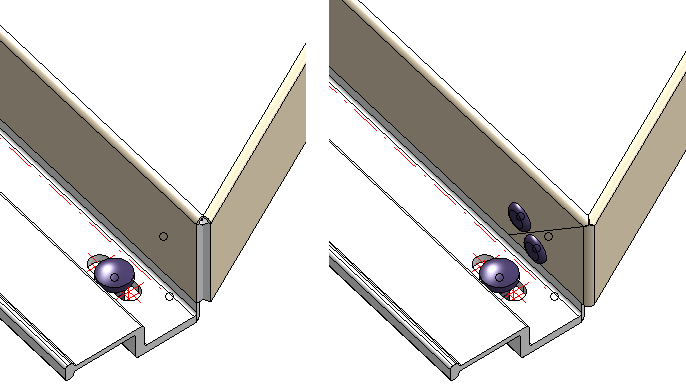
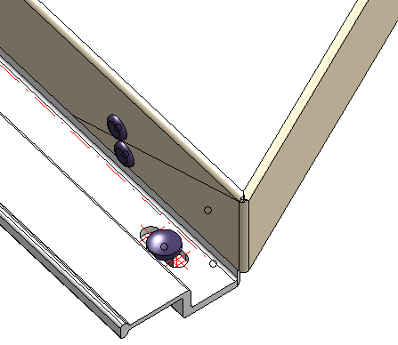
The option Install reinforcing bracket has an effect if the sub-structure is connected to an element installation via the Connection function, which contains elements with attic connection. In this case, the substructure is connected to the rear parapet bracket via angles and riveted: