Project: HiCAD Steel Engineering
'Civil Engineering functions' docking window > Steel Engineering > Connections > Web/Flange to Web/Flange > Cross-bracing (2602)
This Design variant connects
with a cross-bracing. The cross-bracing can be created with a turnbuckle or a tensioning element, and with one or two diagonals.
When connecting beams it is also possible to mount the cross-bracing to already existing plates.
In addition, two beams that are perpendicular to each other can also be connected by cross-bracing with a diagonal.
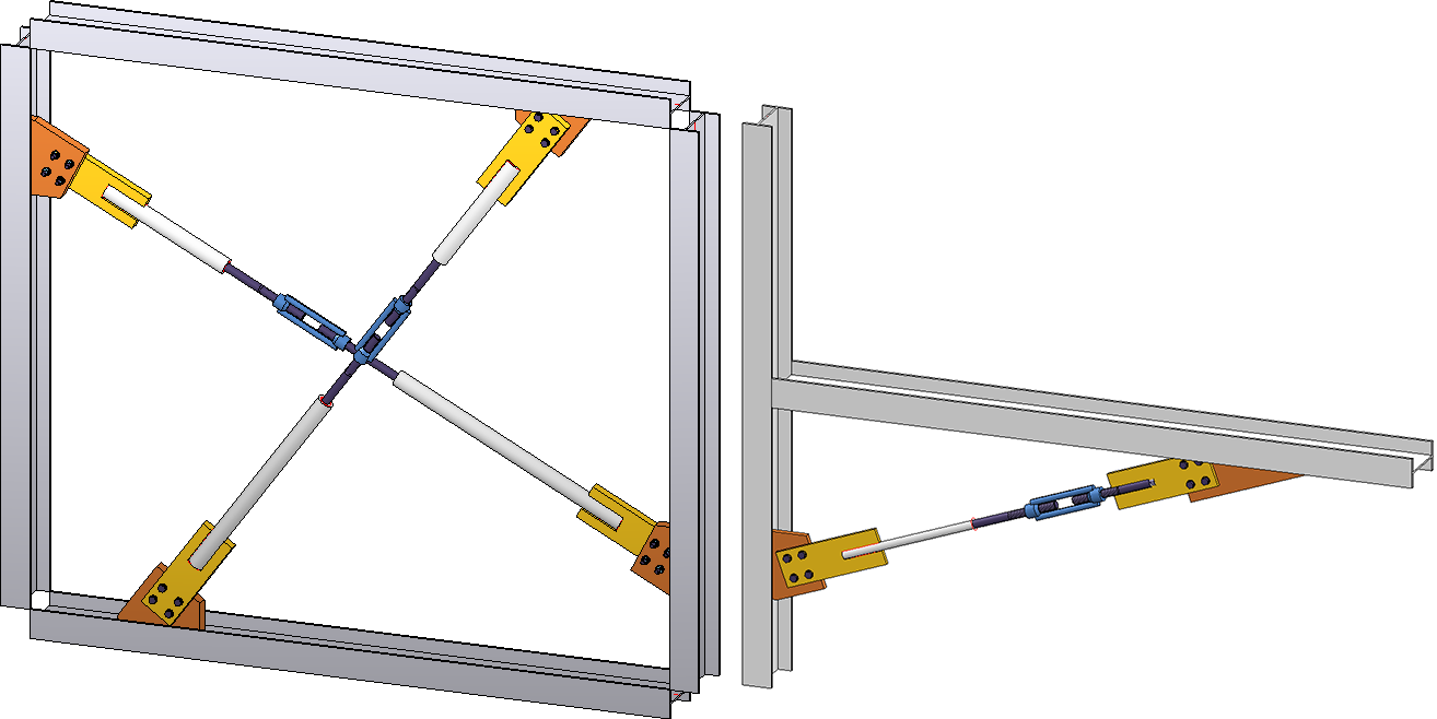
Left: Cross-bracing with turnbuckle - 4 beams, 2 diagonals; Right: Cross-bracing between 2 beams that are perpendicular to each other
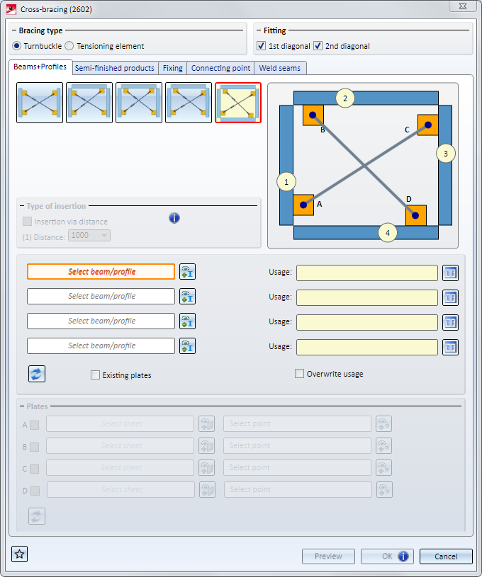
Bracing type
Here you can specify, by activating or deactivating the corresponding radio button, whether the cross-bracing is to be inserted with Turnbuckle or Tensioning element.
Fitting
Here you can specify whether the 1st and/or the 2nd diagonal is to be inserted.
Tabs
The configuration of the cross-bracing is defined on several tabs:
Favourites
The settings in the dialogue window can be saved as Favourites and reused at any time. To do this, click on the  at the bottom left of the window to activate the context menu. More about Favourites management can be found in the Manage Favourites topics of the HiCAD Basics Help.
Buttons
|
Preview |
Shows you a preview of the cross-bracing according to the current settings. You can enlarge or downsize the preview image with the help of the zoom functions. |
|
OK |
Starts the generation of the cross-bracing. The progress of the generation will be shown in a progress bar. After completed generation, the dialogue window will be closed. |
|
Cancel |
Closes the dialogue window without generating the cross-bracing. |
![]() Please note:
Please note:
Please note:
If you process a cross-bracing subsequently (double-click on the relevant Feature), and then select a different number of beams, existing rework and dimensionings on parts of the cross-bracing may be lost. HiCAD will display the following message: 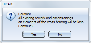

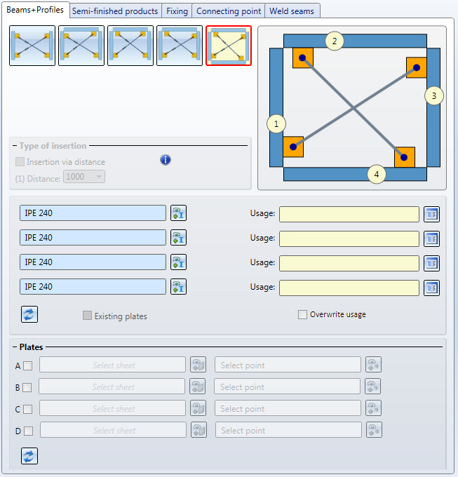
On this tab you specify which beams are to be connected with each other. If you want to connect beams, the connection will automatically provide the gusset plates that are required for this.
But you have also the option to use already existing plates on the beams as gusset plates. This can be useful in situations where you want to insert two cross-bracings between two beams, and mount the second cross-bracing to the gusset plates of the first cross-bracing.
|
|
The cross-bracing will be inserted between 2 beams. Beneath Type of insertion you have the option to specify the distance between the lower edge of the first connecting plate on the beam and the upper edge of the second connecting plate on the beam. If no distance is entered, the insertion will take place in a centred position. |
|
|
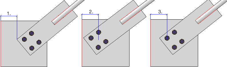
Connects three beams. The first diagonal will be inserted between the beams (1) and (2), the second diagonal wil be inserted between the beams (3) and (1).
|
|
|
Connects three beams. The first diagonal will be inserted between the beams (1) and (2), the second diagonal wil be inserted between the beams (3) and (2).
|
|
|
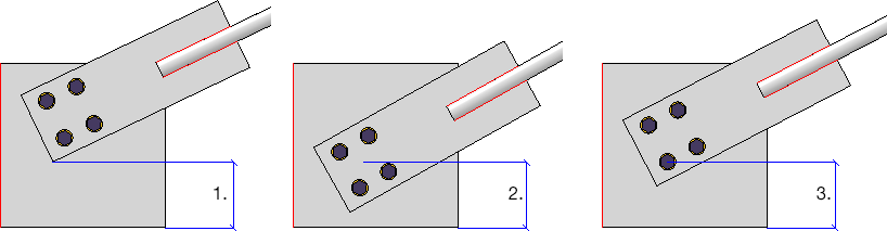
Connects three beams. The first diagonal will be inserted between the beams (1) and (3), the second diagonal wil be inserted between the beams (3) and (2). |
|
|
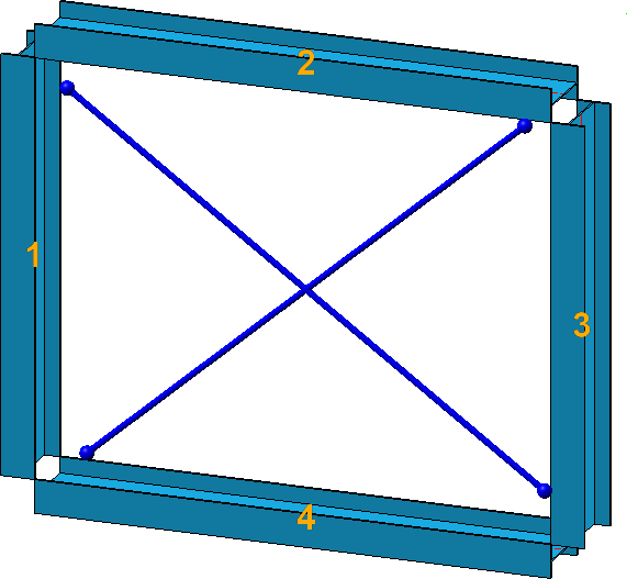
Connects four beams. The first diagonal will be inserted between the beams (1) and (3), the second diagonal wil be inserted between the beams (4) and (2). |
Activate the desired insertion option and select - if required, by clicking on the  symbol - the beams you wish to connect. For each of the beams you can also choose a Usage from the catalogue. If a usage has already been assigned to the assembly of the beam, the Overwrite usage checkbox can be used to specify whether the existing usage is to be kept or replaced by the usage type selected on the Beams + Profiles tab.
 Important:
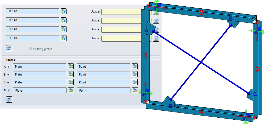
After selecting the beams, they will be visualized in the model drawing - complete with the diagonals.
Click on the  symbol to reset all inputs on the tab.
The connection automatically supplied the gusset plates. But you have also the option to use already existing plates on the beams as gusset plates. This can be useful in situations where you want to insert two cross-bracings between two beams, and mount the second cross-bracing to the gusset plates of the first cross-bracing.
If you want to mount the cross-bracing to plates that already exist on the beams, you can, in addition to the beams, also choose the corresponding plates. To do this, activate the relevant checkboxes beneath Plates, select the plate and specify a point for the centre of the bore grid for the mounting.
Please note the following:
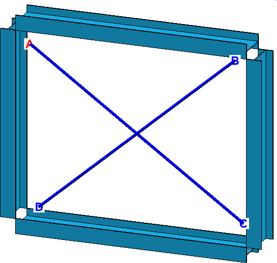
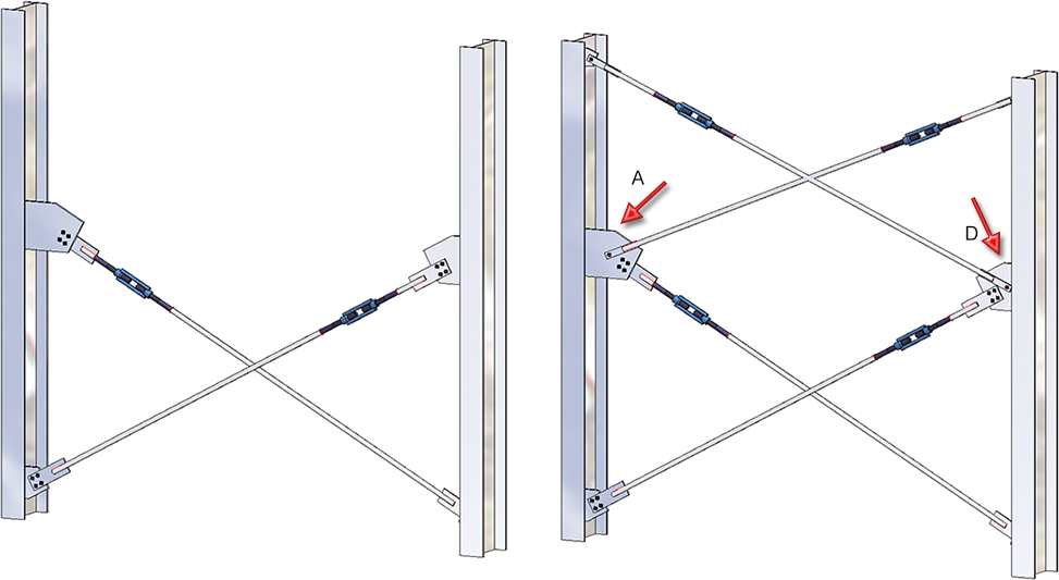
An example:
On the left hand side you can see a cross-bracing inserted between two beams. The gusset plates here were created together with the connection. Then, as you can see on the right hand side, another cross-bracing was inserted between the beams, mounted to the gusset plates of the first cross-bracing (A and D).
If you generally want to insert the cross-bracing between two plates - which have not been assigned to any beams - activate the Existing plates checkbox. Then, activate the corresponding checkbox beneath Plates, select the plate and specify a point for the centre of the bore grid for the mounting.
Please note the following:
 This possibility is now available for the connection type Turnbuckle.
On this tab you can specify
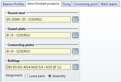
Click on the  symbol to select the semi-finished product directly from the Standard Part catalogues.
Possible semi-finished products are:
|
Standard Part |
Catalogues |
Turnbuckle |
Tensioning element |
|---|---|---|---|
|
Round steel |
Semi-finished products > Beams+Profiles > Round steel |
|
|
|
Gusset plate |
Semi-finished products> Plates Semi-finished products> Beams+Profiles> Flat steel Factory standards > Factory beams > FLUTZ-Profile Factory standards> Factory beams> Frankstahl > A3 Steel bars Factory standards> Factory beams> Frankstahl > C3 Stainless steel bars |
|
|
|
Connecting plate |
Semi-finished products> Plates Semi-finished products> Beams+Profiles > Flat steel Factory standards> Factory beams> FLUTZ profiles Factory standards> Factory beams> Frankstahl > A3 Steel bars Factory standards> Factory beams> Frankstahl > C3 Stainless steel bars |
|
|
Assemble the bolting by clicking on the symbol and selecting the required components in the Bolted/riveted connection dialogue window. Proceed in the same way as you would do for the 3-D function Bolting.
The Boltingwill be inserted as a same-named bolting group. At Assignment: you specify by activating the corresponding radio button, whether this bolting is to be assigned to the assembly of the corresponding beam, or as a loose part that does not belong to any assembly. If you choose "Loose part", the bolting will be inserted on the same structure level as the assembly of the beam.
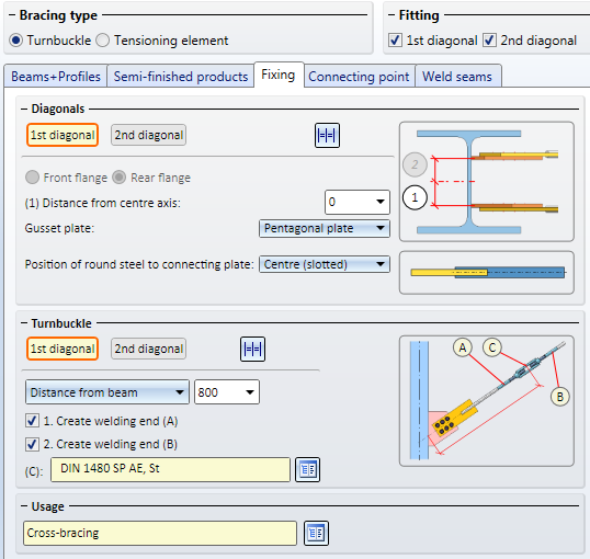
Here you can specify how the diagonals are to be fixed on the beams, and the turnbuckles or tensioning elements to the diagonals.
|
Parameters - Bracing type: Turnbuckle |
|
|---|---|
|
Diagonals |
Here you specify the fixing of the diagonals on the beams. If you want to use the same parameters for both diagonals, click on the |
|
Front flange / Rear flange* |
These options are only available if the Mount to flange checkbox beneath Gusset plate on the Connecting point tab has been activated. |
|
Distance from centre axis* |
You have the additional option to specify the distance from centre axis. This value determines the insertion point of the first plate on the first identified column beam. |
|
Gusset plate* |
You can choose rectangular or pentagonal plates as gusset plates. The dimensions of these plates can be specified on the Connecting point tab. |
|
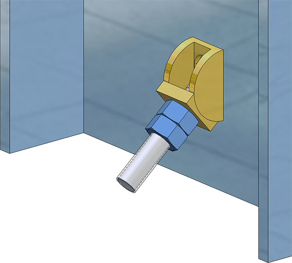
Position of round steel to connecting plate |
Use these options to specify the position of the round steel on the connecting plate - separately for the 1st and 2nd diagonal. Possible are the following positions:
(1) Front, (2) Centre (slotted), (3) Back |
|
Turnbuckle |
Here you specify the fixing of the turnbuckles on the 1st and 2nd diagonal. If you want to use the same parameters for both turnbuckles, click on the |
|
Position of turnbuckle |
With the following options you specify the position of the turnbuckle on the 1st and 2nd diagonal:
|
|
Create welding end (A) and (B) |
Activate or deactivate these checkboxes to determine whether welding ends are to be created or not. The turnbuckle can be created without, with one or with two welding ends. Depending on the position of the turnbuckle, one or two round steels with or without threads will be created as a result.
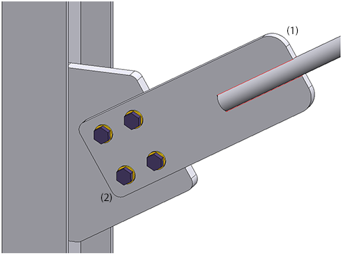
(1) Turnbuckle, (2) Round steel, (3) Welding ends |
|
Select turnbuckle from catalogue |
Here you select the turnbuckle. Click the |
|
Usage |
Here you can assign a usage to a turnbuckle. The default setting is Cross-bracing. |
* These options are not available if plates have been selected on the Beams+Profiles tab.
|
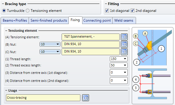
Parameter - Verbandstyp Spannelement |
|
|---|---|
|
Tensioning element |
Here the selected tensioning element will be shown. Click the |
|
Nut |
Here you select the nuts. Click the |
|
Thread length / Thread excess length |
Enter the values for thread length and thread excess length here. |
|
Distance from centre axis (1st/2nd diagonal) |
You have the additional option to specify a distance from the centre axis. |
|
Usage |
Here you can assign a usage to thensioning elements. . |
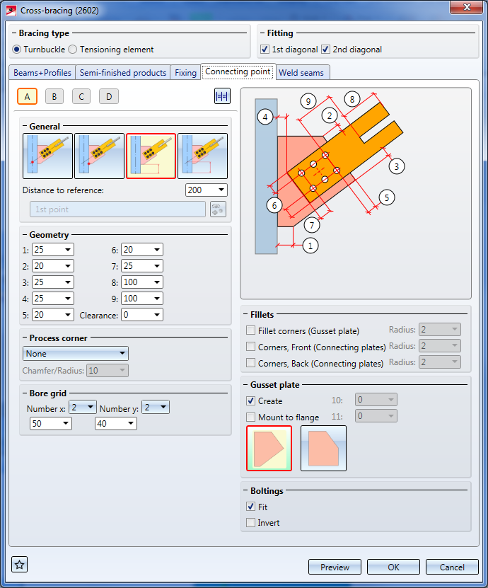
Here you specify how the gusset plates are to be mounted onto the beams, and the connecting plates to the gusset plates. Also, the size of the gusset plates, the position of the bolting and the corner processing for the plates can be specified here.
The setting options on this tab may vary, depending on the gusset plate that was selected on the Fixing tab.
|
Connecting type: Turnbuckle* |
|
|---|---|
|
|
For each of the gusset plates you can specify here
These settings can be specified separately for each gusset plate by clicking on the corresponding number button and defining the required settings. If you want to use the same parameters for all gusset plates, click on the The connection will be visualized in the drawing.
|
|
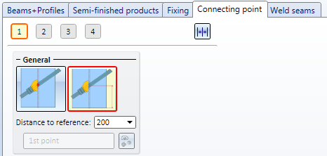
General |
Click on the required symbol to determine how the position of the gusset plate is to be specified - via point selection or distance input. The point selection also influences the assigning of parts to assemblies. If an assembly with the affected beam already exists, the connecting plates will be inserted as sub-parts of the assembly. Otherwise, a new assembly with the affected beam will be created as main part, and the connecting plates will be inserted as sub-parts of this assembly. |
|
|
Point, as intersection point of beam axis and round steel axis |
|
|
Point, as plate start |
|
|
Distance Beam start - Plate start |
|
|
Distance Beam start – Intersection point of beam axis and round steel axis |
|
Geometry |
(1) - (5) determines the geometry of the gusset plates (6) - (9) determines the geometry of the connecting plates In addition, you can specify a clearance between round steel and connecting plate (for Position: Centre (slotted)). |
|
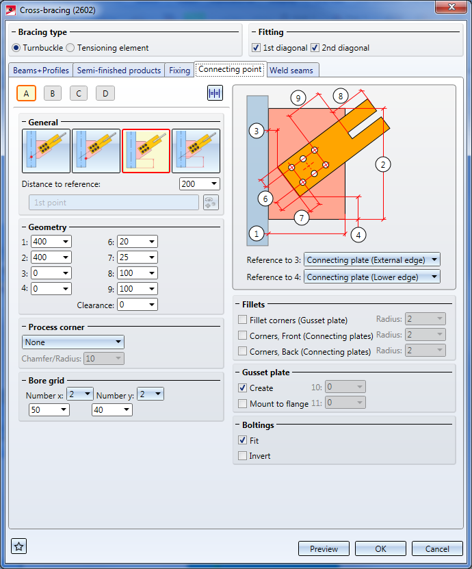
Reference to 3 Reference to 4 |
If you have chosen a rectangular plate as gusset plate on the Fixing tab, you can specify the reference for the values (3) and (4) here in order to influence the position of the connecting plate with reference to the beam/gusset plate. You can choose between the following options: Reference to 3:
Reference to 4:
|
|
Process corner |
If the corner of the gusset plate on the beam is to be chamfered or filleted, you can select the processing type from a listbox. The following corner processings are possible:
|
|
Bore grid |
The bore grid determines the arrangement of the boltings for gusset plate and slotted connecting plate. Enter the number of bores in X- and Y-direction and the distance between the bores. If you want all bores running in one direction to have the same distance, just enter the required distance in one input field and then click on the All equal |
|
Fillets |
Here you can specify whether the corners of the gusset plates and connecting plates are to be filleted. For the connecting plates you can specify different fillet radii for the front (1) and rear corners (2).
|
|
Gusset plate |
In this area you can specify whether gusset plates are to be inserted and, if so, whether they are to be mounted to the beam flange. If this is the case, the options Front flange / Rear flange on the Fixing tab will be available for selection. |
|
Boltings |
Here you specify whether you want to create the bolting or not. Furthermore, you have the option to switch the direction of the bolting by activating the Invert checkbox. |
* Not all options will be available if plates have been selected on the Beams+Profiles tab.
|
Bracing type |
|
|---|---|

|
For each of the tensioning elements you can specify how it is to be mounted to the beam. Click on the corresponding number button to choose the required tensioning element and then specify the desired settings. If you want to use the same parameters for all tensioning elements, click on the |
|
General |
By selecting one of the symbols you specify how the position of the tensioning element is to be determined - via point selection or distance input. |
|
|
Point, as intersection point of beam axis and round steel axis. Specify the required point. The intersection point of the beam axis and the round steel axis will then be located in this point. |
|
|
Distance Beam start – Intersection point of beam axis and round steel axis Enter the required distance. |
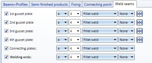
On this tab you can specify for the bracing type Turnbuckle which weld seams are to be created. One distinguishes between weld seams
Activate or deactivate the corresponding checkboxes to specify where weld seams are to be created. For each edge you can set the Type of thickness designation, the Weld seam thickness, the Weld seam type and the Inspection category. If you want to apply the same settings to all gusset plates, click on the Equate  symbol.
For continuous HV and HY weld seams, enter 0 as the weld seam thickness.

Connections + Variants (3-D-SE) • Dialogue Window for Connections (3-D SE) • The Catalogue System for Connections + Variants (3-D SE)
|
© Copyright 1994-2020, ISD Software und Systeme GmbH |
Data protection • Terms and Conditions • Cookies • Contact • Legal notes and Disclaimer