Project: HiCAD Element installation
Civil Engineering functions > Element installation
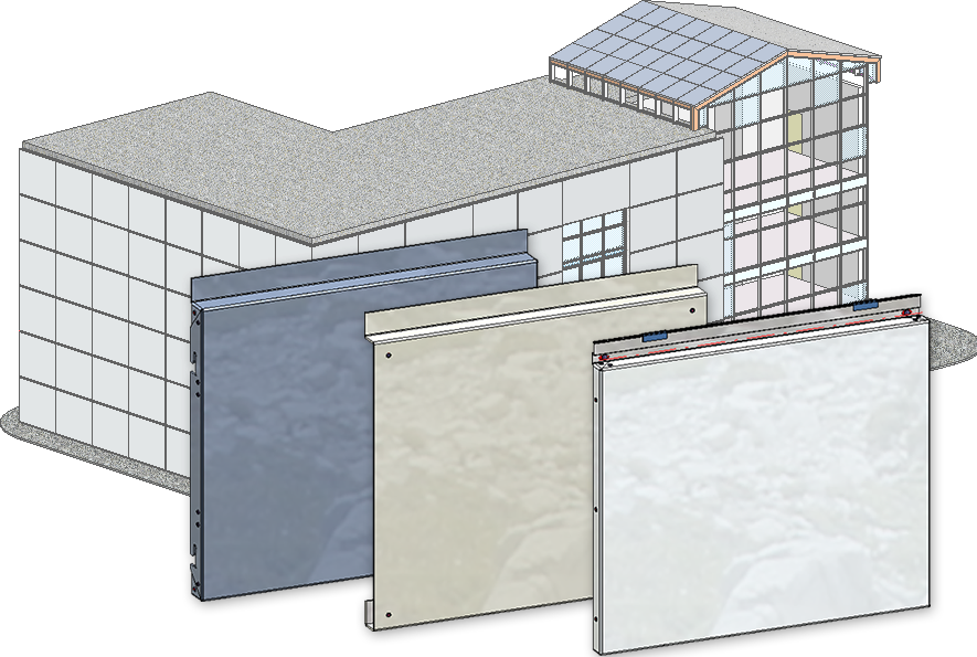
The Element installation is an efficient tool for placing identical parts from the HiCAD catalogue onto areas such as facades, walls, floors etc. Such parts can be sheet metal trays, glass panes, gratings or other catalogue parts.
For instance, you can use the function to clad complete facades with sheet metal tray panels, e.g. ALUCOBOND® panels.
The Element installation functions can be found in the Civil Engineering functions docking window. If the docking window is not visible, activate it via  Settings > Docking window > Civil Engineering functions in the HiCAD Ribbon.
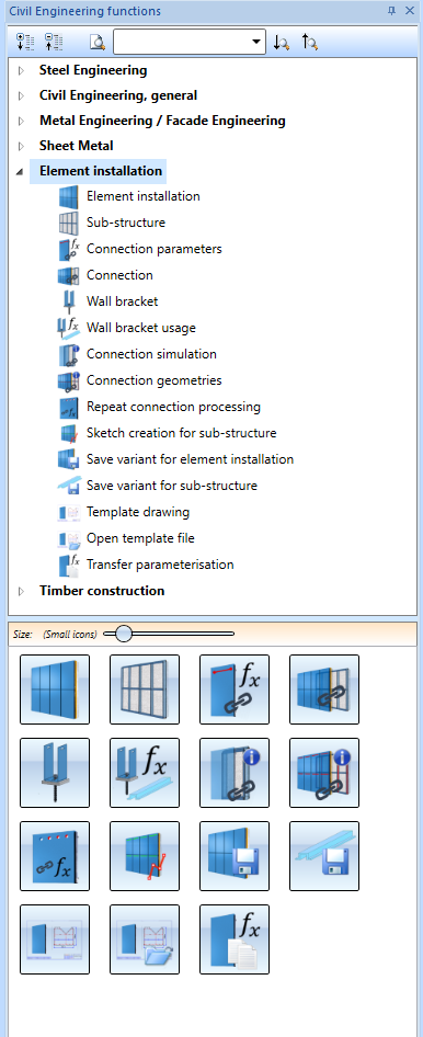
The functions:
|
|
Use the Element installation function to place tray panels and elements with a planar base surface conveniently onto a sketch. |
|
|
Elements that have been installed with the Element installation function must often be mounted to sub-structures consisting of different beams or profiles. The Sub-structure function allows you to place these beams or profiles onto the lines of a sketch. |
|
|
To be able to connect own parts in element installations and sub-structures with the Connection function, these parts must be prepared accordingly. |
|
|
By linking a sub-structure to an element installation you can automatically visualize the mounting of the element installation to the sub-structure in HiCAD. For instance, can create bores and matching fixtures both in element installation and sub-structure. |
|
|
Use this function to automatically create wall brackets for a sub-structure. |
|
|
To be able to place wall brackets in such a way that they match the sub-structure profiles, special information of these profiles must be available. This information can be conveniently defined with this function. |
|
|
While preparing own parts for their connection with the Connection function it can be useful to create the variables that result from the connection for testing purposes before carrying out the actual connection. |
|
|
This function shows the connecting edges of one or several parts and connections. |
|
|
Repeat connection processing Use this function to repeat processings and parameterise them for a use in conjunction with connection parameters. |
|
|
Sketch creation for sub-structure For some element installations it makes sense to apply the structure of a finished element installation to the sub-structure. This function creates a sketch from the finished element installation, which can then be used as a basis for a sub-structure. |
|
|
Save variant for element installation You use this function to save customer-specific installation elements as variants. The prerequisite is that you have constructed and parameterized the corresponding installation element and have defined an Fitting CS for the variant. |
|
|
Save variant for sub-structure You use this function to save customer-specific sub-structures as variants. The prerequisite is that you have created and parameterized the geometry of the sub-structure and defined an Fitting CS for the variant. |
|
|
The Template drawing function allows you to automatically generate individual drawings for a selection or directly for all elements in an element installation. It is possible to create different drawings depending on the configuration of the individual variants. |
|
|
Use this function to open the template drawings belonging to the currently selected part. |
|
|
This function can be used to transfer parameters of an element installation panel to other panels. |


Element Installation: Basic Procedures • Edit Installed Elements • Element Installation: Example • Sub-structure
|
© Copyright 1994-2020, ISD Software und Systeme GmbH |
Data protection • Terms and Conditions • Cookies • Contact • Legal notes and Disclaimer


