Project: HiCAD Element installation
You have the option to automatically create wall holders for sub-structures. For this purpose you can find the Wall brackets function in the Civil Engineering functions docking window.
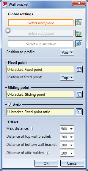
After calling the function the Wall brackets dialogue window will be displayed:
Wall holders are mounted to a wall plane. You select this plane in the Select wall plane field. If the substructure has attics, you can additionally insert a wall bracket for attics. For this purpose you can activate the Select roof plane field and then choose the roof plane. Finally, you select the sub-structure in the Select sub-structure field. Here you have the option to choose the entire assembly of the sub-structure, to attach wall brackets to the entire assembly. Alternatively, you can choose an individual profile of the sub-structure, and attach wall brackets only to this profile.
Use the Position to profile field to determine the horizontal position of the wall brackets with regard to the sub-structure profile. You can choose between Axis, which results in a centred position of the wall brackets beneath the sub-structure profiles (for U-shaped profiles mounted on both sides), Left or Right, which mounts the wall holders on the left or right of the sub-structure profiles (for L-shaped brackets mounted to one side of the sub-structure profile).
For each sub-structure profile, one fixed point and several sliding points are applied. You can choose one wall bracket for the Fixed point and the Sliding point from the catalogue. Furthermore, you can specify via the Position of fixed point field where the fixed point is to be placed on the sub-structure profile: Top, Middle or Bottom. Please note that if you choose Middle, the fixed point will actually not be placed exactly in the middle of the sub-structure, but the mounting point that is located closest to the middle will be made the fixed point.
If you use an Attic, activate the same-named checkbox and choose an additional bracket for the attic. In this case, a wall plane needs to be selected.
In the Offset area you can influence the vertical distances of the wall brackets. Use the Distance of top wall bracket and Distance of bottom wall bracket fields to specify the den exact distance of the top or bottom bracket from the top or bottom edge of the wall or the sub-structure profile. In between, wall brackets will be applied, with equal distances not exceeding the specified Max. distance.
If you use an Attic, and have activated the same-named checkbox, you can also specify the Distance of attic holder. This value controls the exact distance of the attic holder from the front edge of the roof.

Besides using the supplied wall brackets, you can also define and insert your own wall brackets.
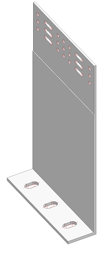
Wall brackets are normal parts that are saved in the catalogue. They require a Fitting CS which will be placed on the fitting point. The X-axis points crosswise to the profile direction, or, in the case of wall brackets mounted on one side, away from the profile. The Y-axis then points in profile direction.
For creating mounting drawings, a named point "!" will be required, for which the dimensions will be created.
In the present example, a wall bracket for the Purchased/Factory standard parts for a usage of Wall bracket is to be prepared.
Choose 3-D Standard > Standard Parts > BoltScrew  > Purchased/Factory standard parts and insert a wall bracket into a model drawing. In this case, select Wall consoles > Systea > L-Wall consoles > WB2 40/80/3-160.
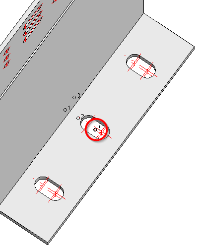
These parts contain 3 isolated points, which are perfectly suited for defining the Fitting CS. Open the context menu in the still empty Feature log of the wall bracket and choose Switch feature on. Then, select Drawing > Others > World CS > Define Fitting CS. HiCAD will then prompt you to specify the 3 points: Origin, Point in X-direction, Point in Y-direction. Choose the 3 points as shown in the graphic.
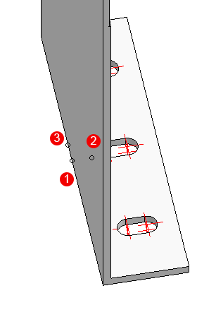
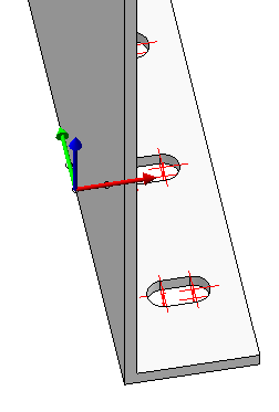
Points for the Fitting CS: (1) Origin, (2) Point in X-direction, (3) Point in Y-direction. The result can be seen on the right.
For dimensioning in mounting drawings an additional named point "!" must exist, in relation to which the dimensions will be created. This point can be located in the origin, but also elsewhere. In this case the dimension point should be in the centre of the middle bore.
Choose 3-D Standard > Tools > New point to place an isolated point in the centre of the middle bore. Then, choose 3-D Standard > Tools > Point > New point number, identify the point you have just created and assign the point name "!" to it.
You can then save the finished part to the catalogue: Choose Drawing > Save/Reference > Reference part, Save, Detail drawing. In the dialogue window, select the option Save as part with catalogue entry and save the part to the catalogue beneath Installation planning - Parts and Processings > Sub-structure> Wall bracket.
You can now insert the wall brackets.
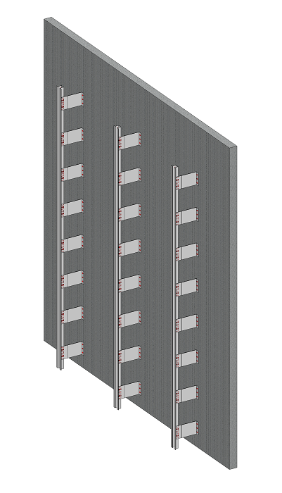
The result: Your own wall brackets on a sub-structure
Adjustments made manually to wall brackets, such as moving or deleting individual consoles, are retained even after the wall brackets have been recalculated. In case you want to discard your changes, the context menu of the Wall bracket entry in the feature log provides the function Restore, which discards all adjustments and re-generates all wall brackets.

Create Own Profiles for Sub-structures • Customizing the Dialogue Window
|
© Copyright 1994-2020, ISD Software und Systeme GmbH |
Data protection • Terms and Conditions • Cookies • Contact • Legal notes and Disclaimer