Project: HiCAD Element installation
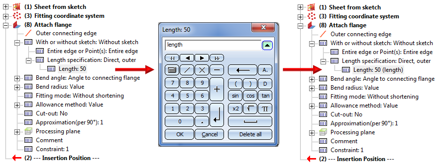
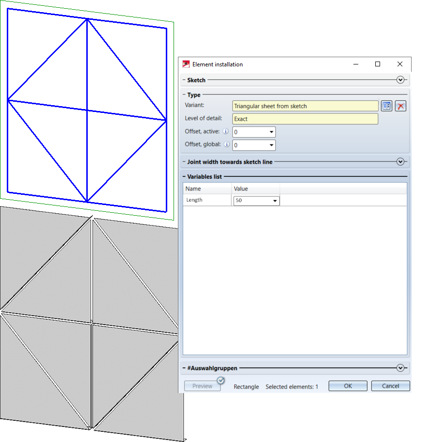
In the following example an non-rectangular installation element will be created - a triangular sheet with an attached flange. The sheet is to be derived from a sketch, and the length of the flange is to be variable.
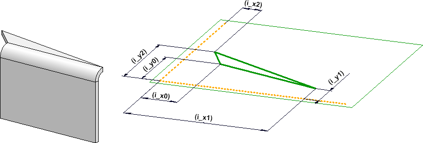
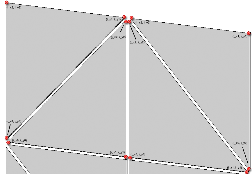
As already mentioned, non-rectangular elements must be parameterized via the x- and y-distances of their corner points to the origin of the Fitting CS. In the process, the order of the points will be mathematically positive, i.e. anticlockwise.
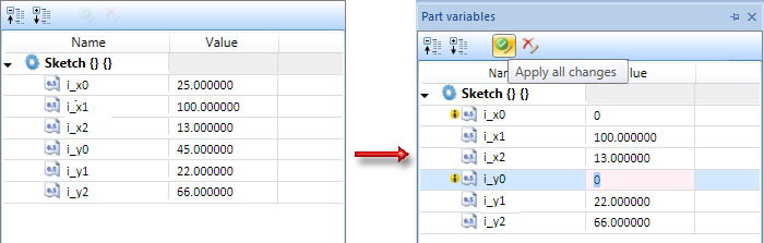
For the sheet in our example this means that you need to assign the variables (i_x0,i_y0), to the first point, the variables (i_x1,i_y1) to the second point, and the variables (x2, y2) to the third point.
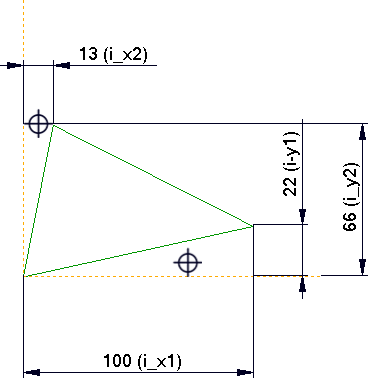
Left: Installation element "Sheet with flange"; Right: Original sketch for the sheet

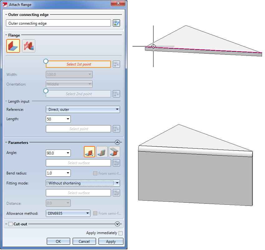
The first step is the construction of the installation element. For our example, this comprises the creation and parameterization of the sketch, deriving of the sheet and attaching of the flange.
 Please always make sure that Feature creation is active.
 to create a new sketch.
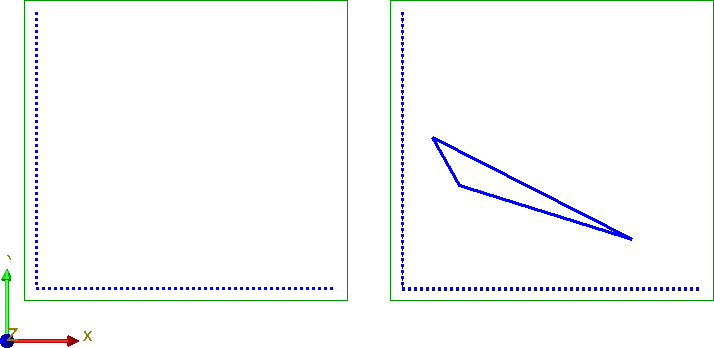
  to draw two lines as shown below - one parallel to the Y-axis, the other one parallel to the X-axis. You will need these lines as an auxiliary geometry for parameterization, i.e. they virtually symbolize the coordinate system for the corner points of the triangle that you want to draw.
  > Auxiliary geometry
  and select the two lines. They will then be displayed as dashed lines.
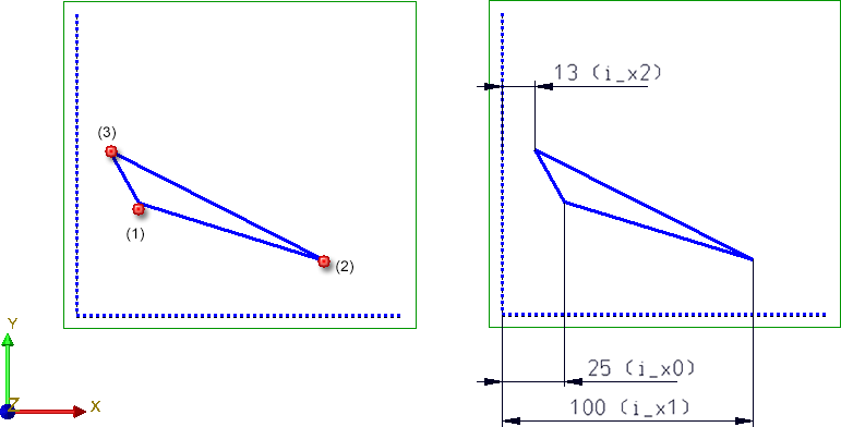
 and specify the distance constraints of the 3 corners to the vertical auxiliary line (HCM scaling = Scale complete sketch). Choose i_x0, i_x1 and i_x2 as variables.
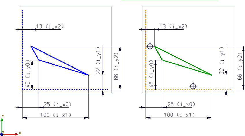
 and select the two lines of the auxiliary geometry.
 Apply all changes.
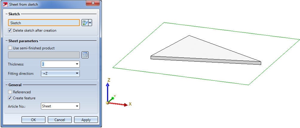
 , select the sketch, enter the sheet thickness and close the dialogue window with OK.
 .
.
The Fitting CS determines the insertion direction of a part in space. It consists of 3 special points:
If a 3-D part to which a Fitting CS has been assigned is loaded into a new model drawing, the points of the Fitting CS will be placed into the World CS. In this way the insertion direction in space will be determined.
The definition of a Fitting CS is of particular importance if the installation element is an assembly. If this assembly is saved to the Element installation catalogue while no Fitting CS is assigned to it, the Part CS will be used as Fitting CS when the part is inserted. However, this may lead to unwanted results during the installing process.
 Please note:
Not all assemblies have automatically a Feature log. For instance, this applies to assemblies that have been created with the Form assembly function, or via New > Assembly. If you assign a Fitting CS to these assemblies, no corresponding Feature log entry will be generated. To achieve this, you must assign a so-called body creation feature to the assembly. To do this, right-click on the Feature window of the assembly and select the corresponding function in the context menu. After this, the definition of the Fitting CS will be entered as a Feature here, too.
Continuation of the example:
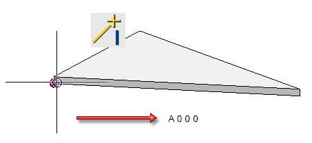
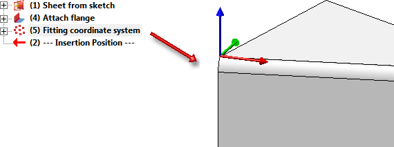
As already mentioned, the sheet in this example is to be inserted in such a way that the first corner (i_x0,i_y0) lies in the bottom left corner of the selected sketch area. Therefore, a Fitting CS must be defined for the Sheet Metal main part.
Choose Drawing > Others > World CS > Define Fitting CS  and proceed as follows:
(1) New origin of coordinate system is the bottom left corner of the sheet, i.e. Absolute 0 0 0.
(2) Point on X-axis: R (Relative) 200 0 0
(3) Point on y-axis: R (Relative) 0 200 0
The Fitting CS will be entered into the Feature log.
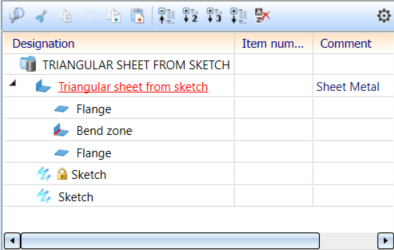
The installation element has been completed and can now be saved to the catalogue.
To save the installation element as a variant, choose Element installation > Save variant for element installation in the Civil Engineering functions docking window.
Please make sure that the Sheet Metal main part is active here.
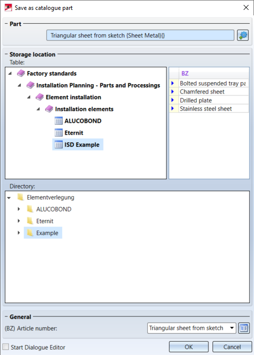
The HiCAD folder KATALOGE now contains the files
at Werksnormen\Elementverlegung\Example.

Element Installation • Catalogue Editor
|
© Copyright 1994-2020, ISD Software und Systeme GmbH |
Data protection • Terms and Conditions • Cookies • Contact • Legal notes and Disclaimer