Project: HiCAD Element installation
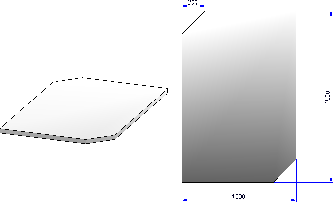
In the following description a chamfered sheet will be used as installation element. In the installation process this sheet is to be inserted in such a way that the chamfers are located at the top left and the bottom right (in principle, the sheet has a polygonal shape, but will be treated like a rectangular sheet since the basic element has a rectangular shape).

This is the first step towards the creation of your own installation element. Construct the part using the appropriate HiCAD functions.
 Make sure that Feature creation has been activated!
Example:
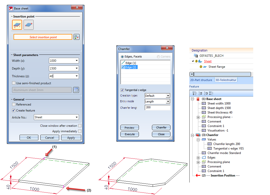
Activate the Sheet Metal tab and choose New > Base  . Create a base sheet with the following dimensions: Width = 1000, Depth = 1500 and Thickness = 40.
Switch to the 3-D Standard tab and choose Process > Chamfer  to chamfer the edges (1) and (2) with a length of 200.
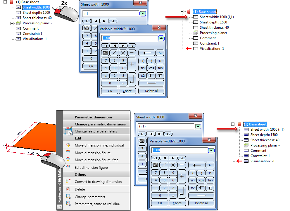
To ensure that the installation element can be automatically adjusted to the utilized sketch during element installation it needs to be parameterized. Parameterization takes places by means of variables and formulas and - if required - by assigning of HCM constraints.
In any case, the variables
must be used for the width and height of the installation element!
You can assign these variables either
Some functions also allow a direct use of variables.
Continue as follows:
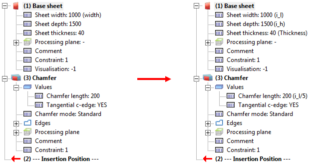
Now, parameterize the chamfered sheet. Since the sheet is to be inserted in such a way that the chamfers are located at the top left and the bottom right, you need to assign the variable i_l to the width of the sheet. Also, the chamfer length is to be always 1/5 of the width. In addition, we require a variable sheet thickness, individually selectable in the Element installation dialogue window.
Important:
If the installation element is an assembly, all utilized variables need to be assigned to this assembly!
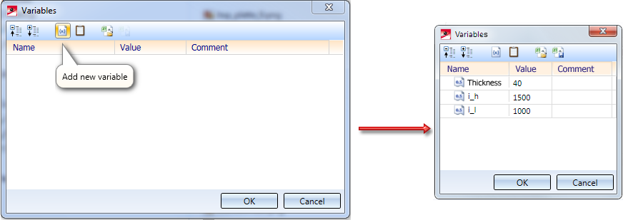
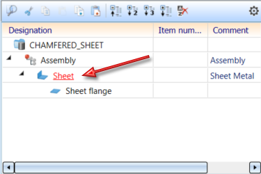
Let us assume that the sheet shown above belongs to an assembly, and that the assembly is to be used as an installation element. In this case the parameters i_l, i_h and Thickness must be assigned to the assembly. To do this, right-click the name of the assembly in the ICN and select Properties > Part variables. Then, select Add new variable in the Variables dialogue window and enter the name of the variable and its initial value.
You can then parameterize the base sheet as described above.
The Fitting CS determines the fitting direction of a part in space. It consists of 3 special points:
If a 3-D part to which a Fitting CS has been assigned is loaded into a new model drawing, the points of the Fitting CS will be placed into the World CS. In this way the fitting direction in space will be determined.
The definition of a Fitting CS is of particular importance if the installed element is an assembly. If this assembly is saved to the Element installation catalogue with no Fitting CS assigned to it, the Part CS of the assembly will be used as the Fitting CS during insertion. However, this can lead to unwanted results during placing of elements.
 Please note:
Not all assemblies will always have a Feature log. This applies, for instance, to assemblies that are created with the Form assembly function, or with the Assembly, new function. If you assign a Fitting CS to those assemblies, no Feature entry will be created for this. To achieve the creation of a Feature entry, you need to assign a body creation feature to the assembly. To do this, right-click in the Feature window of the assembly and select Enter body creation feature. After this, the definition of the Fitting CS will be entered as a Feature here, too.
Continue as follows:
As already mentioned, the example sheet is to be inserted in such a way that the chamfers are located at the top left and the bottom right. Therefore, you need to define a Fitting CS for the Sheet Metal main part.
On the Drawing tab, select Others > World CS  > Define Fitting CS
  . Use the function as follows:
(1) Origin of coordinate system
(2) Point on X-.axis
(3) Point on Y-axis
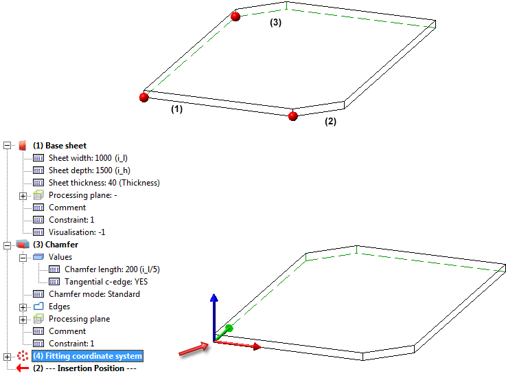
The Fitting CS will be entered in the Feature log.
The installation element has now been completed and can be saved to the catalogue.
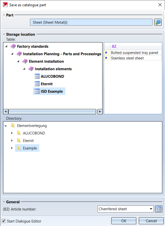
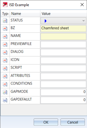
To save the installation element as a variant, choose Element installation > Save variant for element installation in the Civil Engineering functions docking window.
Please make sure that the Sheet Metal main part is active here.
 symbol to define the contents of the table columns for the sheet metal (for example, to specify a preview image).
at Werksnormen\Elementverlegung\Example.
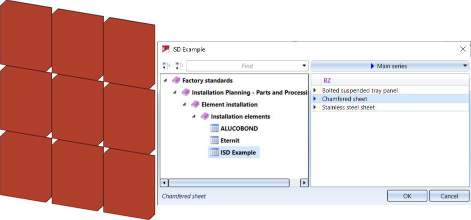
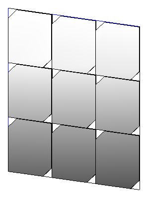
Result:

Element Installation • Catalogue Editor
|
© Copyright 1994-2020, ISD Software und Systeme GmbH |
Data protection • Terms and Conditions • Cookies • Contact • Legal notes and Disclaimer