Workshop Drawing - Views/View Groups to Be Created
Drawing > Itemisation/Detailing > Drawing derivation 
The pre-settings of the dialogue windows can be specified in the Configuration Editor at Automatic drawing derivation.
Views to be created
In the Drawing parameters area of the Derive drawing dialogue window, you can specify in the Views to be created for: field which views you would like to create for
- Assemblies, Railings
- Beams,
- Plates,
- Sheets,
- General parts.
The Views for... dialogue window is displayed (here: Views for assemblies).
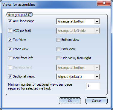
To assign views to a view group, activate the corresponding checkboxes.
- Axonometric views can be arranged by choosing the desired option from the list boxes (top, bottom, left, right).
- Sectional views for assemblies, railings, beams, profiles, Steel Engineering plates and general 3-D parts can be arranged as follows:
- Aligned (default)
- In columns, to the left or right of the view group
- In rows, above or below the view group.
The total height of the view group changes when the arrangement in columns and rows is selected.
In addition, you can select the minimum number of sectional views per page that is required for the selected arrangement method.
If the Sectional views checkbox has been activated ion the Views for assemblies dialogue window, you can specify in the settings for view groups whether sectional views are also to be created for attached parts. According to the ISD default setting, sectional views are automatically created for Steel Engineering plates running transversely or diagonally to the main part axis. When working with configuration templates, you can specify for each usage which sectional views are to be created for attached parts. The setting can be defined in the Configuration Editor at Automatic drawing derivation > Production drawing > Usage-dependent > name > View group, with name being the name of the relevant template.
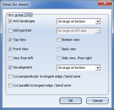
- For Sheet Metal parts you have the additional option to display developments and sectional views by activating the relevant checkboxes.
- Development
The development view can be arranged at the top, the bottom, on the right or left within the view group. When working with usage-dependent configuration templates, the arrangement chosen in the corresponding template will be preset. This presetting can be changed in the Configuration Editor at Automatic drawing derivation > Production drawing > Usage-dependent > name > View group, with name being the name of the relevant template. There you can choose the desired arrangement via the parameter Sheet development: Position in view group. - Sectional views
The section for creating the sectional view takes place at the shortest bending zone. The sectional views are created with depth limitation and are applied perpendicular to the bending zone. Please note that continuous sectional views are only created if the bending zone is parallel or perpendicular to the view CS.
The following views are available:
|
Part type |
Axonometric view |
Sectional view |
Development |
Standard views |
|---|---|---|---|---|
|
Assemblies |
landscape or portrait |
yes |
- |
all |
|
Beams |
landscape or portrait |
- |
- |
all |
|
Plates |
landscape or portrait |
- |
- |
all |
|
Sheets |
landscape or portrait |
- |
yes |
top, bottom, left, right |
|
General parts |
landscape or portrait |
|
|
all |
If you work with configuration templates, the following views will be pre-set in the Views for... dialogue window:
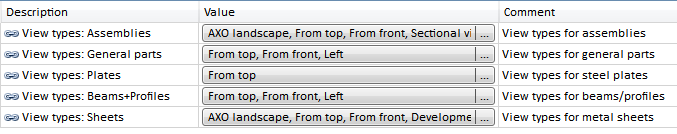
The pre-settings can be specified in the Configuration Editor at Automatic drawing derivation > Production drawing > Usage-dependent > name > View type assignment, Parts, with name being the name of the respective template.
 Please note:
Views in derived drawings can be locked in such a way that they can no longer be rotated out of the screen plane. Some view functions will then be unavailable for locked views, namely, all functions that would cause a rotation of the view out of the screen plane, e.g.:
- Standard views
- Axonometries and Isometries
- Transform to required position, etc.
These functions will be hidden in the transparent toolbar, and greyed out in the Ribbon as well as in the context menu.
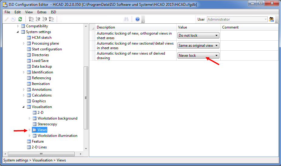
To activate the locking of views in derived drawings, open the Configuration Editor (ISDConfigEditor.exe) and select ...> System settings > Visualisation > Views, and set the parameter Automatic locking of new views of derived drawing to Always lock. The default setting is Never lock.
To unlock individual views of the derived drawing, open the context menu of the view and select Unlock  . To unlock all views of the derived drawing, set the above parameter in the Configuration Editor to Never lock and re-generate the drawing.

View groups to be created
In the workshop drawing, detail groups are managed in so-called "view groups". The structure of these view groups is specified via the checkboxes shown below.
- Main parts as assembly
One view group is entered for each assembly main part, and each main part which is not assigned to any assembly. Sub-parts which are assigned to a main part, i.e. plates, connections, bolts etc. are also taken over into the view group. - Main parts, individually
If this checkbox is active, one view group for each main part is entered into the workshop drawing. Sub-parts such as plates, connections, bolts etc. are only taken over into the workshop drawing if the Sub-parts, individually checkbox is active. - Sub-parts, individually
If this checkbox is active, one view group for each sub-part is entered in the workshop drawing.
Use the buttons of the Views to be created for: area to specify the views for a view group.
Example of a workshop drawing with 3 view groups
Please note:
- Main parts that do not belong to an assembly, i.e. parts on the highest level of the part structure, will only be considered for production drawings if the Main parts, individually checkbox beneath View groups to be created for: in the Drawing derivation dialogue window was activated.
- For each view group creation, whether for a part or an assembly, the assigned usage will be evaluated.
- If a drawing-relevant assembly (e.g. an assembly with an assembly main part) has been assigned a usage, the drawing configuration will be determined via the usage of the assembly main part.
- If a drawing-relevant assembly (e.g. an assembly with an assembly main part) has not been assigned a usage, HiCAD will check whether the assembly main part has been assigned a usage. If this is the case, the drawing configuration for assembly views will be determined via the usage of the assembly main part.
- If a part of a drawing-relevant assembly has been assigned a usage, the drawing configuration for part views will be determined via the usage of this part.
- If a part of an assembly (assembly main part or normal part) has not been assigned a usage, the DEFAULT configuration will be used.

Derive Drawing • Settings for Derived Drawings (3-D SE) • Derived Drawings - Settings for Drawing Sheets etc. • Usage-Dependent Configurations