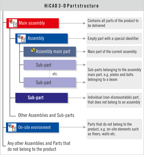
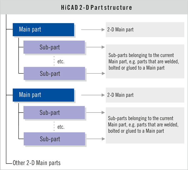
A HiCAD Drawing basically consists of 2-D and 3-D parts, which can be single Parts, or Assemblies. In HiCAD one distinguishes between Main parts and Sub-parts. This provides the basis for a reasonable Part structure.
Main parts and Sub-parts
Main parts are parts that exist independently of other parts in the drawing. Sub-parts are parts that belong to other parts in the drawing, e.g. parts that are welded or bolted to other parts. For instance, bores or bolts always belong to a workpiece, i.e. they are sub-parts to a main part. Several sub-parts can belong to a main part, and sub-parts can in turn contain more sub-parts.
Assemblies and Main assemblies
For further structuring of 3-D drawings, you use Main assemblies and normal Assemblies in HiCAD.
An Assembly is a part with a special assembly identifier. This identifier provides additional efficiency for itemisation, identical part search, BOM generation and the utilisation of HELiOS.
A Main assembly is a special assembly to which all other assemblies of the product to be created are subordinated, and which contains the article master of the Drawing when you are working with the PDM system HELiOS. A 3-D drawing cam contain only one Main assembly.
Part structure
The subdivision of the drawing into Main assembly, Assemblies, main parts and Sub-parts - in the following referred to as "part structure" - provides the user with a part-oriented data structure. This enables the creation of CAD model drawings the logical structure of which corresponds to the structure of real products, consisting of one main assembly, (sub-)assemblies and individual parts.
Other objects and information
For a further detailing of the drawing, or to facilitate the designing process, further objects are added to the geometry of the assemblies, main parts and sub-part. Some examples:
- Dimensionings and Texts (2-D and 3-D)
- Processing planes (3-D)
Normally, the drawing plane is the screen plane. In 3-D CAD, however, you can select any other drawing plane by defining a so-called "processing plane". - Views (3-D)
A so-called "view" is a projection, i.e. a two-dimensional representation of 3-D objects. On e distinguishes between standard views (top view, side view, front view...), isometric and axonometric views. - Pixel graphics
You have also the option to insert, besides the already described drawing objects, pixel graphics (e.g. company logos) in your drawing. - Drawing frame and title block
HiCAD provides drawing frames with title blocks in various DIN formats. These can be inserted in your drawings. - Grids and auxiliary lines
You can use 2-D and 3-D grids and 2-D auxiliary lines as construction aids. - Clipboard contents
Texts, graphics and Excel tables can be inserted in the HiCAD drawing via the clipboard. - In addition, the drawing contains information on
- the coordinate system, the scale and the unit of measurement,
- the 2-D graphical elements and points,
- the 3-D solids, surfaces, edges and points,
- the hatchings,
- the materials used and
- the non-graphical elements (attributes, article data).

Part Structure: Advantags and Planning • Part Structure Representation in the ICN • Teile/Baugruppen bearbeiten


