Settings for Boltings/Rivetings
3-D Standard > Standard Parts > Bolting  > Settings
Use this function to specify the settings for the insertion of boltings and rivetings.
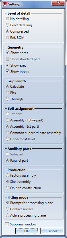
The settings beneath Level of detail and Geometry determine the representation of the boltings.
Level of detail
If Exact detailing had been chosen, the bolt heads are represented in detail. Especially for large drawings containing very many boltings it often makes sense to use the Compressed (2) representation to increase the performance of the program. If you want boltings (including their nuts and washers) in compressed representation to be considered for identical part search, BOM creation, or product structure transfer to HELiOS, select the Ref. BOM (3) representation.
 For Compressed representation, the display in the ICN will be changed accordingly.
Geometry
Bores, standard parts, axes and threads can be shown or hidden by activating or deactivating the corresponding checkboxes.
Grip length
There are three methods for determining the effective length of a bolting:
- Calculate
The effective length is calculated automatically by HiCAD. - Pick
Determination by copying a distance from your drawing. The Distances menu is displayed to determine the effective length. - Through
The effective length results from the height of the parts to be bolted together.
Bolt assignment
You use these options to define the assignment of standard parts in the part structure.
- 1st part*
A sub-part called "Bolted connection" will be assigned to the part that you identified first in the insertion process. This sub-part consists of further sub-parts containing the bolts, the nuts and washers etc. The structuring of these further sub-parts depends on the settings in the Auxiliary parts area of the dialogue window.
If individual standard parts are inserted, this option is identical to Active part.
- Assembly (Active part)
If an assembly is active when you call the function, or if the active part belongs to an assembly, the bolted connection (or the individual standard part) will be assigned as a new assembly called "Bolted connection" to this assembly. If the active part belongs to no assembly, the "Bolted connection" assembly will be placed at the uppermost level of the part structure.
The "Bolted connection" assembly consists of several sub-parts such as bolts or washers. The structuring of these sub-parts depends on the settings in the Auxiliary parts area of the dialogue window.
- Assembly (1st part)
The bolted connection (or individual standard part) will be inserted as a new assembly with the name "Bolted connection. This is the default setting. The structuring of this assembly depends on the settings in the Auxiliary parts area of the dialogue window.
If the 1st selected part belongs to an assembly, the "Bolted connection" assembly will also be assigned to the assembly of the 1st part. If the 1st selected part belongs to no assembly, the "Bolted connection" assembly will be placed at the uppermost level of the part structure.
This is the default setting. The structuring of the new assembly depends on the settings in the Auxiliary parts area of the dialogue window.
- Common superordinate assembly
Here, a common, superordinate assembly for the two selected parts will be used. To this assembly with the name "Bolted connection", the bolted connection (or the individual standard part) will be assigned.
- Uppermost level
The bolted connection (or the individual standard part) will be placed as a new assembly with the name "Bolted connection" at the uppermost level of the part structure.
This option makes sense if, for instance, you want to bolt parts together that are located in locked assemblies.
If this option is deactivated, and the assembly in which the bolting is to be created is locked, the following message will be displayed:
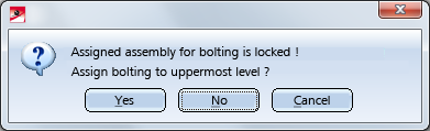
If you select Yes, the bolting will be placed at the uppermost level of the part structure. You can avoid this query by activating the Uppermost level option right from the start.
Auxiliary parts
Here you can specify the position of the auxiliary parts of a bolting, such as washers or nuts, within the part structure.
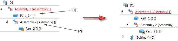
- Sub-part *
The "Bolted connection" part consists of sub-parts the names of which are automatically generated by HiCAD, depending on the selected bolt (or screw) standard and its dimensions. Nuts and washers are assigned to them as sub-parts.
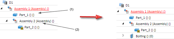
- Parallel part
The auxiliary parts are located in a sub-part called "Bolting". This part contains - on the same level - the bolt (or screw), the washer and the nut.
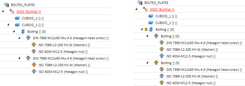
Example of a bolted connection, consisting of 2 boltings. Left: Auxiliary part = Sub-part; Right: Auxiliary part = Parallel part
Production
Use these options to determine the production type. Possible options are:
- Factory assembly,
- Site assembly,
- On-site construction.
Fitting mode
Here, you specify the plane for the fitting.
- Prompt for processing plane
Before fitting a standard part, you are prompted for the definition/identification of a processing plane. - Contact surface
The system searches for a common surface with another part. - Active processing plane
The currently active processing plane is used. If no processing plane is active, the fitting is made perpendicularly to the xy-plane of the active coordinate system.
Suppress window
The corresponding setting window is normally displayed each time a fitting function is called. If you do not want this to happen, activate the Suppress window checkbox. If you want to make subsequent changes to the settings, you will need to activate the relevant setting function explicitly.
OK / Cancel
Click OK, to save the current settings as the new default settings. Click Cancel to end the function without applying the changed settings.
Please note:
When inserting bolts in an auto-generated assembly in Steel or Metal Engineering, the dimensions of the assembly will be determined by the production type specified in the settings for bolts. If Site assembly has been selected, the part dimensions will not be changed by the insertion of the standard part, i.e. the dimensions will then correspond to the shipping dimensions.
 Important:
In the Configuration Editor (ISDConfigEditor.exe) at Modelling > Change of part structure, the parameter Main parts and sub-parts automatically in assemblies is set to Yes... by default. This means that the options
- Bolt assignment - 1st part
- Auxiliary parts - Sub-part
will be greyed out, i.e. the default setting is Bolt assignment: Assembly (1st part) and Auxiliary parts: Parallel part.


Standard Parts, Boltings, Rivetings, Weld Seams (3-D) • Boltings and Rivetings (3-D)