
Project: HiCAD 2-D
The previous "CS display" toolbar has been extended with additional functions for fast hiding and showing of objects and renamed to Visualisation. With the new functions you can, among others, enable/disable the visibility of isolated points and 2D dimensions with one click. This allows for example to hide all dimensions of a drawing without having to call a function from the context menu or ribbon first..
|
|
Toggle visibility of isolated points AAll isolated points and the point identification of the construction can be switched on/off with one click. |
|
|
Toggle visibility of dimensions All 2-D and 3-D dimensions of a drawing can be switched on/off with one click. This applies to both drawing dimensions and parameter dimensions. |
The Autopilot settings toolbar below the drawing area can now be used to control which points the autopilot offers as snap points. In the toolbar the possible snap points are highlighted.

With this bar you can control which point options should be visible on the Autopilot by activating / deactivating the icons. For example, if you click on  , the snapping of isolated points is disabled.
The currently selected Autopilot settings apply to the active HiCAD session. You can define which settings should be active when restarting HiCAD in the Configuration Editor at System settings > Identification > List of point snap options.
If you click on the  icon in the Autopilot settings toolbar, the settings from the Configuration Editor are restored.
Scales in HiCAD are used as
The scale can be selected from a selection box in the corresponding HiCAD function dialogues. In addition, in many cases it is also possible to enter a scale directly. The scales available in the selection boxes of the HiCAD functions are defined in the file szene-massstab.txt in the HiCAD subdirectory makro2d for 2D parts. Please note that HiCAD supports the European scale logic by default, i.e. scale specifications in the form n:m, e.g. 1:1, 1:10, 5:1 etc

However, the US scale logic differs from that in Europe. Therefore HiCAD offers the possibility to extend the file szene-massstab.txt accordingly by defining further scale specifications.
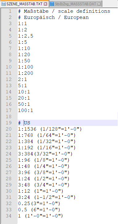
Example of an expanded szene-massstab.txt file
' foot, " inch, 1 foot = 12 inches, 1 inch = 2,54 cm
Changing the file szene-massstab.txt
To structure the file, any empty lines and comments can be inserted, whereby comment lines must begin with the # character. Each scale specification must be in a separate line. The following notations are supported for the scale specification.
|
Notation |
Examples |
|
|---|---|---|
|
1. |
Specification in the scale format n:m |
1:10 1:1 2:1 5:1 |
|
Specification as factor |
0.1 1 2 5 |
|
|
As factor with display text The factor is at the beginning of the line, the display text in brackets behind it. The display text is used by HiCAD in dialogues and info messages. |
2.5 (2‘-6“ = 1‘-0“) 1 (1`-0“ = 1‘-0“) |
|
|
4. |
In the scale format with display text The scale is at the beginning of the line, the display text in brackets behind it. The display text is used by HiCAD in dialogues and info messages. |
1:12 (1“=1‘-0“) 1:48 (1/4“ = 1‘-0“) |
Notations 3 and 4 are suitable for US scale specifications.
![]() Please note:
Please note:
Further information on Definition of Scales can be found in the same named topic in the Basics Help.
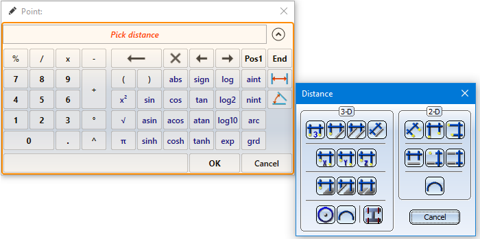
The HiCAD pocket calculator has been redesigned.
In many cases HiCAD offers a default value which you can either apply or modify. You end the value input
Special keys:
The two buttons for  Distances and
  Angles are used to transfer from existing construction objects.
Alternatively, you can call these functions in the context menu, which you activate in the calculator input field with the right mouse button. The functions of the Distance and Angle menu displayed here correspond to the functions with the same name in the Information menu.
The point option (PW) Point from point cloud  is now also available in the 2-D point options menu. The point option can also be called via the keyboard by pressing the C key.
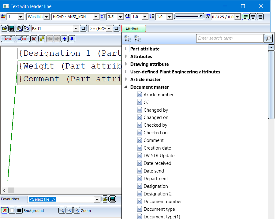
When selecting attributes for annotations, you can mark frequently used attributes as favourites for faster access. To do this, simply click on the  symbol next to the attribute name. The symbol then turns yellow
  . Attributes marked in this way are listed in the selection window under Favourites.
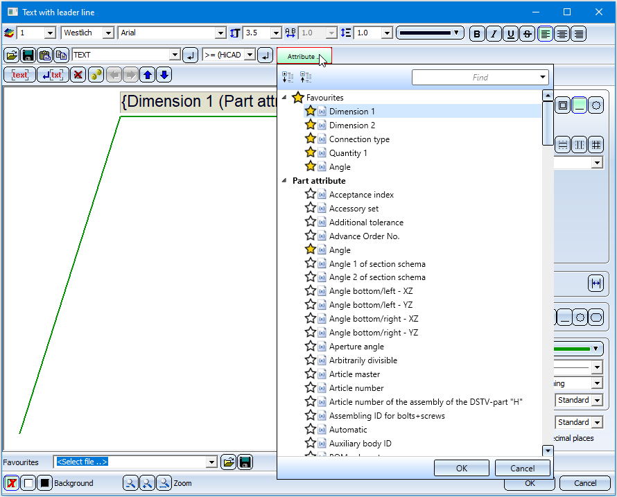
To remove an attribute from the favorites list, simply click on the corresponding symbol - either directly in the Favourites list or in the attributes list.
When drawing with the 2-D geometry functions, the Autopilot - depending on the cursor position - now also displays the point options
 (O) Online on edge through point and
 (F) Perpendicular base point
is displayed when the cursor is near a straight line.
If the cursor is near a circle, the (F) Perpendicular base point and (T) Tangential point options are now also displayed. For arcs and ellipses the behaviour is the same.
From SP1 onwards, all information on the surface finish is displayed in the same font size and line width. After a new installation of HiCAD, the default setting for the text height of the surface symbols in the file SURFSYM.INI 3.5 mm.
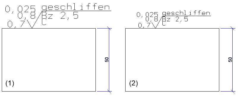
(1) before HiCAD 2020 SP1
(2) from HiCAD 2020 SP1 onwards
Pixel graphics - such as company logos - in the formats BMP, GIF, PCX, TIF and JPG as well as EMF files (Enhanced Meta Files) can be inserted either with the function Drawing > Insert Part > Exp...  > Bitmap or with CTRL+V from the clipboard into the current HiCAD model drawing. They are assigned to the 2-D part structure and have the name _B_M_P__.
The internal behaviour of these two procedures was different until now. From HiCAD 2020 SP1 onwards the two procedures have been unified and stabilized. This means, in particular, that checking the 2-D part structure via Information > Check > 2-D Geometry no longer indicates errors if the model drawing contains pixel graphics.
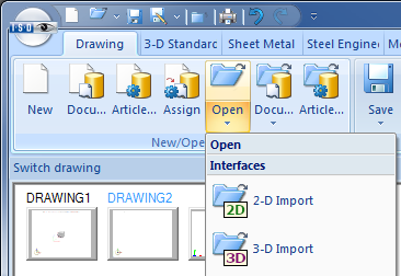
When importing 2-D/3-D drawings via interfaces, HiCAD 2020 will distinguish between 2-D and 3-D imports. For this purpose the previous function Drawing > New/Open > STEP, IGES, ... has been split into two new functions:
The Attributes button is now available for selecting attributes in the label editor. After clicking on this button the selection list for attributes is displayed, which is divided into different attribute groups.
The default settings for fonts can now be set separately for 2-D and 3-D text in the Configuration Editor. The corresponding parameters can be found there at Drawing > Annotations Text.

HiCAD (2-D) • General Information (2-D)
|
© Copyright 1994-2020, ISD Software und Systeme GmbH |
Data protection • Terms and Conditions • Cookies • Contact • Legal notes and Disclaimer

