Project: HiCAD Dach/Wand/Fassade
Civil Engineering functions > Element installation > Element installation
Use the Element installation function to place tray panels and elements with a planar base onto planar sketches.
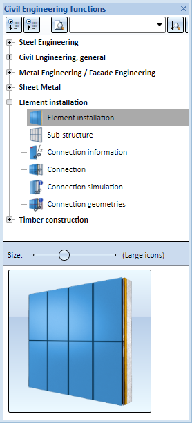
You can find the function in the Civil Engineering functions docking window beneath Element installation.
The Civil Engineering functions docking window
A prerequisite for element installation is the existence of a planar sketch, which serves, so to speak, as a "planning grid" for the installation. You can choose between the following installation types:
Furthermore, you have the option to use variable installation elements by using the part variable i_nr. You assign a number of corners n to this variable. In this way it is ensured that these installation elements are adjusted to sketch areas with a maximum of n corners and thus can be installed there. For instance, if the i_nr variable is set to 5, the installation element can be installed on sketch areas with 3, 4 and 5 corners. Further information on the i_nr variable can be found here.
Please note that element installation works only for sketch areas that have no gaps, are not nested and have no double lines. Each of these sketch areas stands for one installed element.
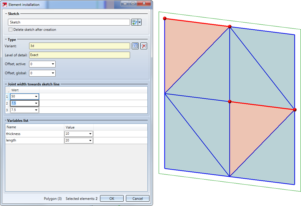
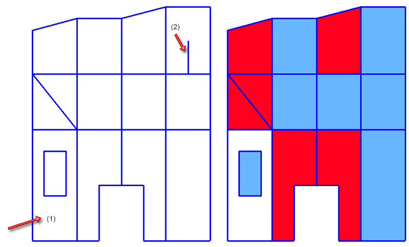
In the sketch shown below, for instance, you can place "rectangular" installation elements on the blue areas, and polygonal installation elements on the red areas. Area (1) and the lines (2) will be ignored.
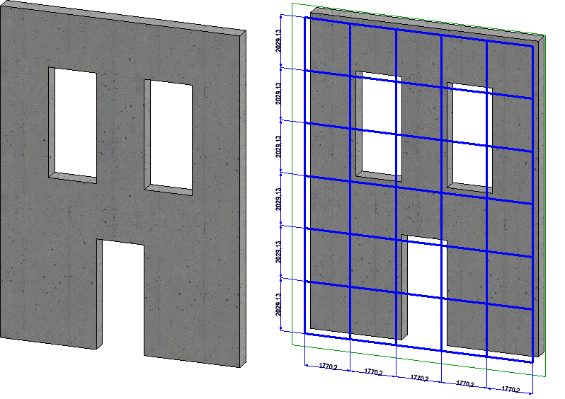
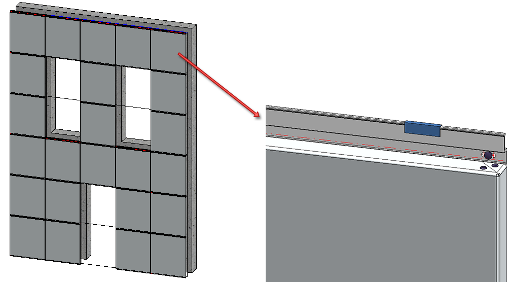
In the example below, ALUCOBOND® tray panels SZ-20 are to be placed on the shown sketch.
The procedure for element installation consists of the following steps:
![]() Please note:
Please note:
|
|
Element that will not be considered (e.g. in case of nestings or areas with gaps) |
|
|
Active element, i.e. the element on which the cursor points |
|
|
Selected element, not occupied yet (Special colour Marking 5, Semi-transparent) |
|
|
Selected, already occupied element (Special colour Marking 5) |
|
|
Unselected element, not occupied yet (Special colour Preview, Semi-transparent) |
|
|
Unselected, but already occupied element (Special colour Preview) |

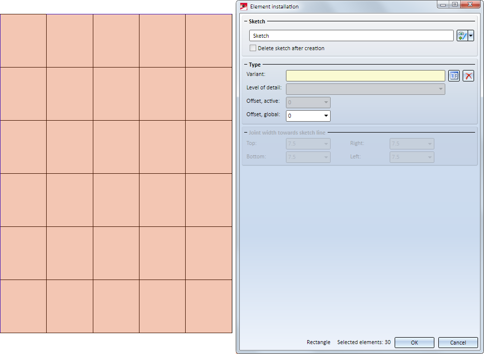
When you call the function, HiCAD will ask you to select the sketch. Then, the Element installation window will be opened and all empty sketch areas where elements can be placed will be shown in light blue. Here, all areas are initially empty.
Click  to select the required sketch. Clicking the arrow symbol
  opens a menu with the following functions:
|
|
Process sketch
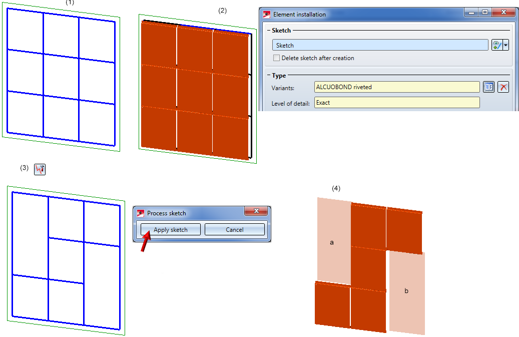
Modify the sketch as required and, in the dialogue window, click Apply sketch. The dialogue window will from then on refer to the changed sketch. Please note the following:
Example: In the image below the Sketch (1) has been selected. For all sketch areas (2) the variant ALUCOBOND riveted has been selected, but the calculation has not been started yet. If you now process the sketch as shown below (3) and then apply it (4), the variant needs to be reassigned for the sketch areas a and b.
|
|
|
New sketch in plane
|
If you want the original sketch to be removed from the drawing after the installation of the elements, activate the Delete sketch after creation checkbox.
![]() Please note:
Please note:
If the selected sketch contains double edges, this will be indicated by the  symbol in the dialogue window:
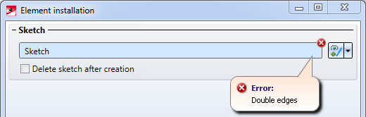
Such cases require a removal of the double edges before executing the function; to do this, choose Sketch > Process > Del.  > Delete double lines.
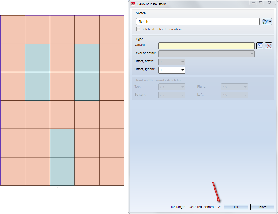
For each of the permissible elements the element installation settings can be individually specified. HiCAD will prompt you to select the elements to be edited, i.e. the sketch areas onto which the elements are to be placed.
You have now the following options:
You can also mark several elements:
In this example no elements are to be installed in the areas reserved for door and windows. Since all permitted elements are marked after calling the function, press and hold down the CTRL key and click to exclude the window and door elements from the selection, one by one.
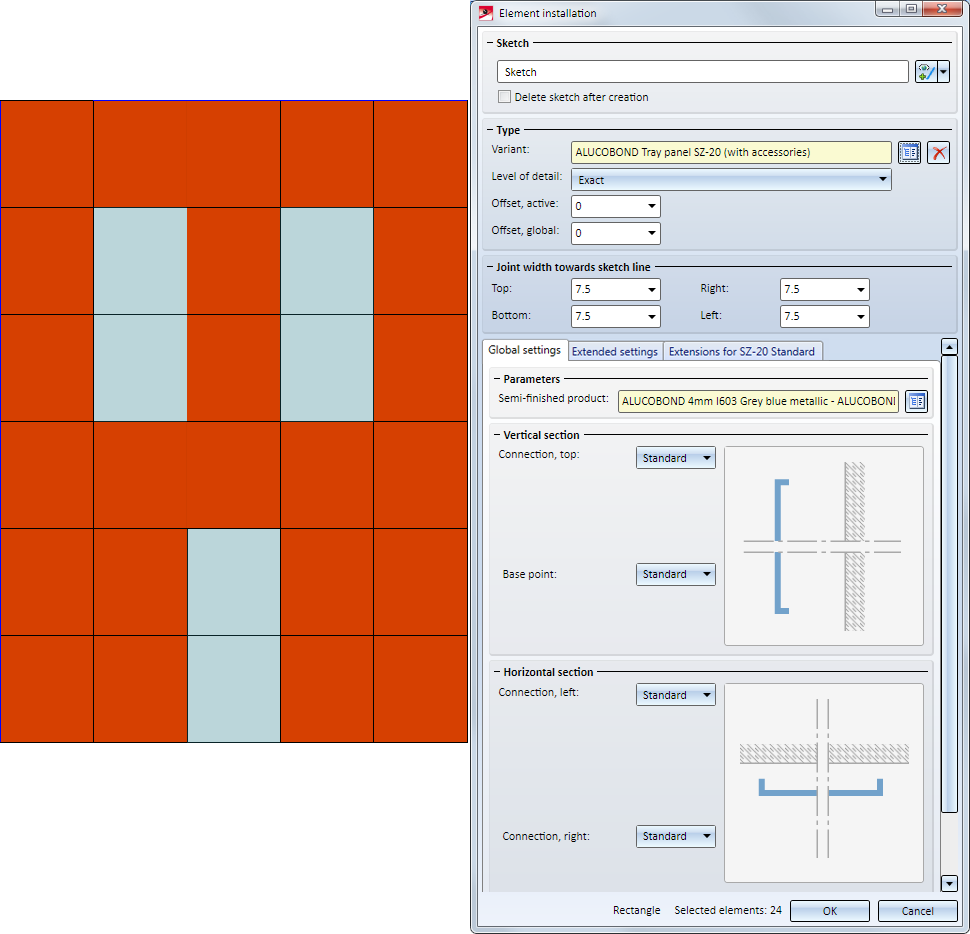
Then, choose the variant ALUCOBOND Tray panel SZ-20 (with accessories).
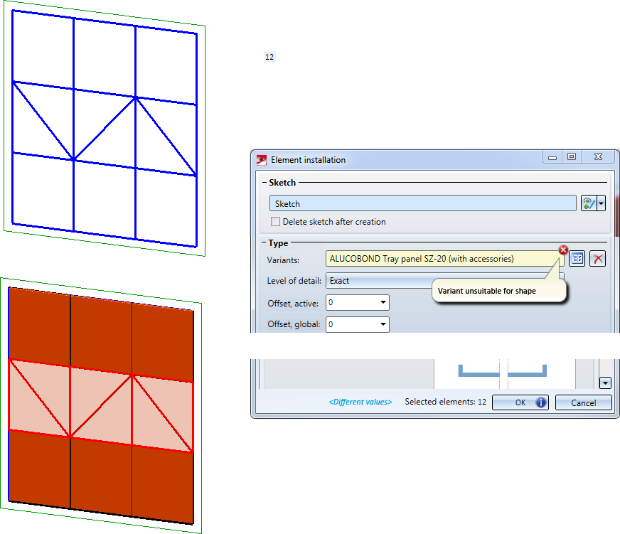
![]() Please note:
Please note:
symbol in the input field for variants, and the  symbol on the OK button. In the drawing the corresponding sketch areas will be highlighted.
Then, change the selection.
The following settings for individual elements are possible:
|
Variants |
Here you can choose the desired variant. Click on the |
|
Level of detail |
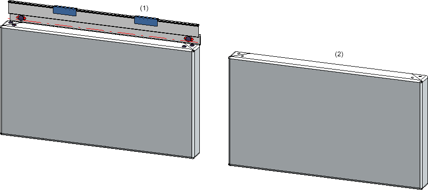
ALUCOBOND Tray panels SZ-20 and ALUCOBOND suspended tray panels can be displayed in the Exact mode or in the Draft mode. The representation as a draft can make sense if you want to speed processes up for model drawings containing very many tray panels. The representation can be switched at any time during processing of the installed elements.
(1) Exact representation, (2) Draft
The settings for the trays (e.g. attic data) will be preserved while you switch between representations. This is also true for subsequently applied processings, dimensionings and annotations. |
|
Offset, active |
This value determines the offset of the installation element from the sketch. If the value is positive, the installation element will be placed above or behind the sketch. If the the value is negative, the installation element will be placed below or in front of the sketch. |
|
Offset, global |
This function works in the same way as the Offset, active function, with the difference that it refers not only to the active element, but to all elements of the installation. Accordingly, this setting can only be changed globally, i.e. for all elements at once. If a global offset has been defined and, additionally, an individual offset for one single element, the two offsets will be added for this single element. |
|
Joint width towards sketch line |
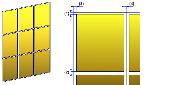
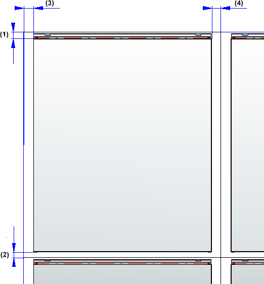
Here you can define the joint widths - separately for top, bottom, right and left - i.e. the distances of am installation element from the edges of the corresponding sketch area.
Joint width: (1) top, (2) bottom, (3) left, (4) right For ALUCOBOND Liner tray SZ-20 with accessories, the joint width always refers to the liner tray.
|
The other setting options depend on the selected variant.
The Element installation dialogue window always displays the settings for the currently selected element.
With the exception of the offset we apply the default settings in this example and start the calculation.
Use the  button to activate or deactivate the generation of previews. By default, the checkbox is active, that is, a new preview will be generated each time you change an entry in the dialogue window.
For a more fluent working with large sub-structures you can remove the checkmark from the button. After this, a preview will only be displayed if you explicitly click on the button (i.e. previews will no longer be generated automatically).
After defining the settings for the selected elements, start the calculation with OK.
During the calculation process, the

symbol will be shown. After completion of the calculation the dialogue window will be closed automatically.
If the calculation cannot be performed, the  will be shown on the OK button. When you move the cursor over the symbol, a short error description will be displayed.
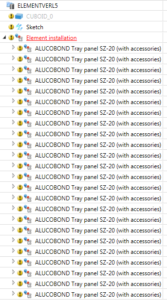
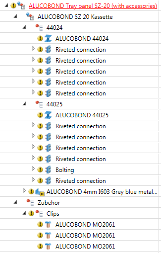
The installation elements that have been inserted in the process will be combined into one assembly called Element installation. In our example, this looks as follows:
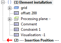
At the same time, a feature called Element installation will be created and entered in the Feature log.
 Please note:
If installation elements are referenced, the Element installation feature will be deleted. This means that an editing via the Element installation dialogue window will no longer be possible.

Edit Installed Elements • Element Installation: Example
|
© Copyright 1994-2019, ISD Software und Systeme GmbH |


 symbol and choose the desired installation element from one of the catalogues, e.g. ALUCOBOND®, or a customer-specific installation element. Click