Project: HiCAD Dach/Wand/Fassade
The Element installation module (for which you need a separate license) provides you with a multitude of 3-D variants of ALUCOBOND®-specific tray panels. In addition, a wide range of ALUCOBOND® semi-finished products enable an effortless integration of the desired surface and colour variants.
An interface to the production department can be created by adding the ALUCOBOND®-specific allowance methods to the production data in HiCAD and passing them automatically to the CNC machines in the production department (see also the HiCAD Sheet Metal Help).
ALUCOBOND installation elements
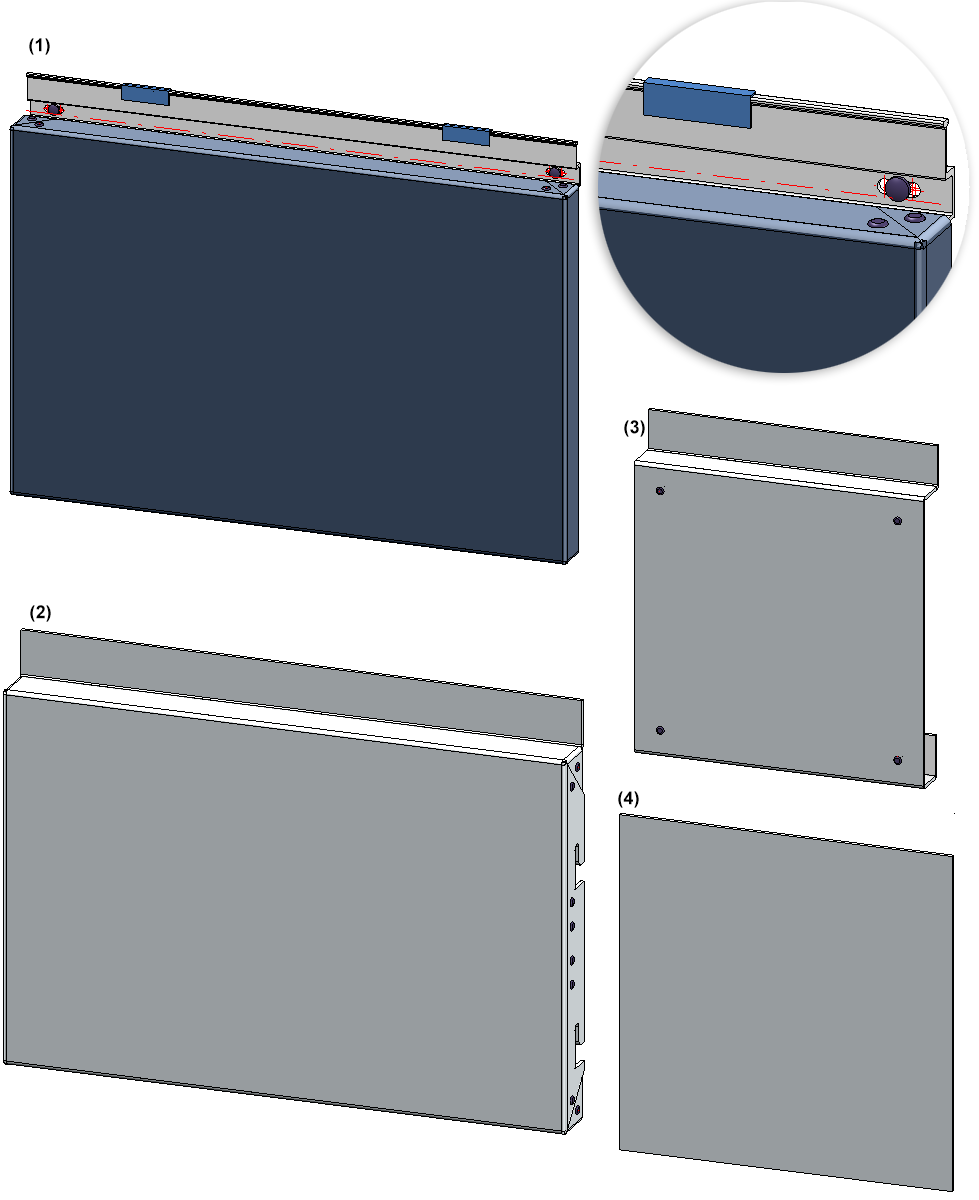
ALUCOBOND installation elements: (1) Tray panel SZ-20, (2) Suspended, (3) Riveted, (4) Bonded
 Please note:
Please note:
Which installation elements are available depends on the HiCAD software license you are using. For instance, if you want to insert ALUCOBOND® tray panels in your model drawing you will need a HiCAD ALUCOBOND® suite or the Element Installation module in conjunction with the ALUCOBOND ® Tray Panels Standard Parts Package.
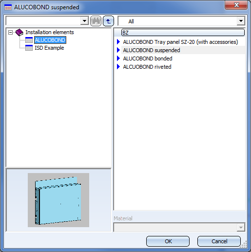
You can find the ALUCOBOND installation elements in the catalogue Factory standards > Installation Planning - Parts and Processings > Element installation > Installation elements > ALUCOBOND.
The contents of the dialogue windows vary depending on the chosen installation element.

In the dialogue window for the ALUCOBOND Tray panel SZ-20 (with accessories) you can find 3 tabs with setting options:
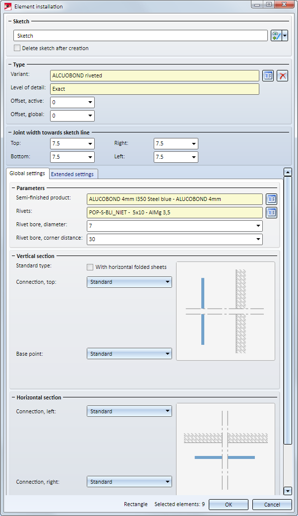
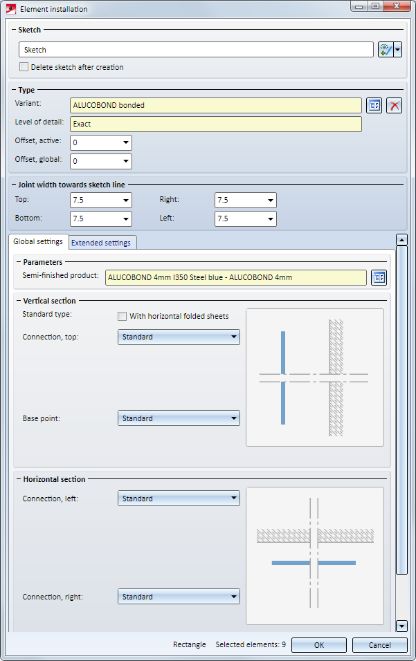
Global settings
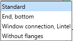
Here you can choose the desired semi-fnished product and the parameters for Connection, top, Base point, Connection, left and Connection, right.
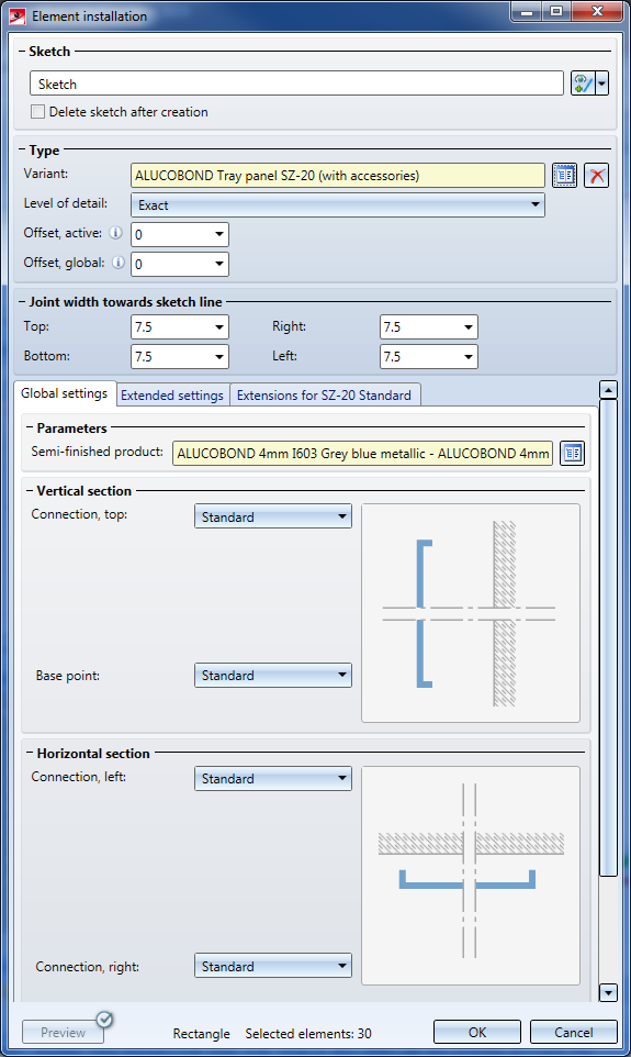
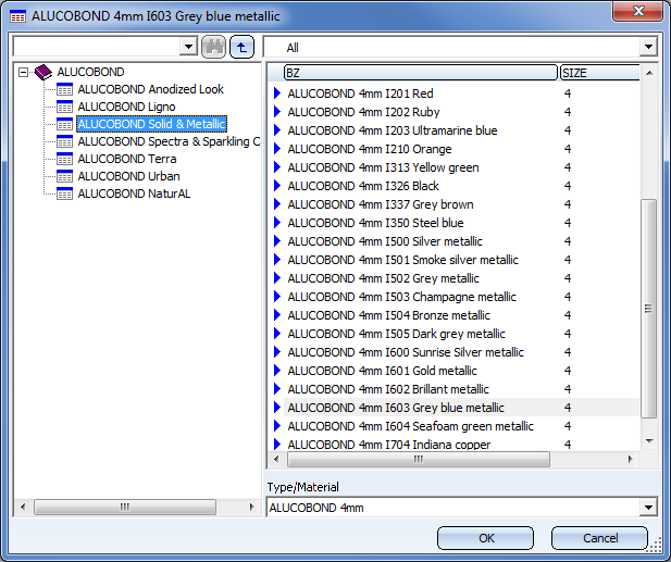
Selection of ALUCOBOND Semi-finished products:
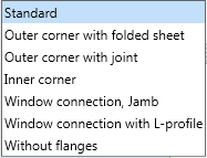
Possible connection options:
|
Horizontal section |
|||
|
Top |
|
Base point |
|
|
Vertical section |
|||
|
Left |
|
Right |
|
Depending on the chosen connection type, further input fields may be displayed.
If you choose Connection, top: Window connection, parapet beneath Vertical section when installing ALUCOBOND®Tray panels SZ-20, an additional angular L-bracket will be used for the connection.
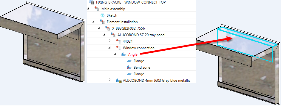
If you connect such an element installation with a sub-structure, the sub-structure will be shortened appropriately. Also, bores will be applied to the sub-structure and the fixing brackets.
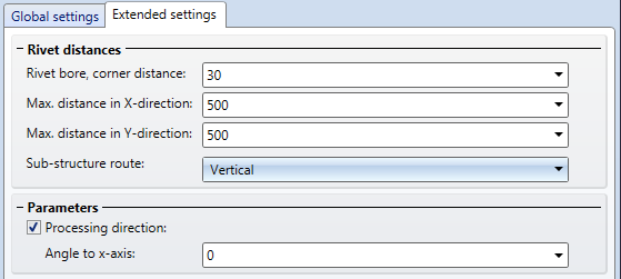
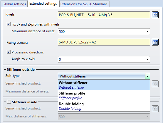
Extended settings
On this tab you specify the processing types for the suspension (S- and Z-)profiles and stiffeners.
First, select the rivets and screws for the mounting of the profiles to the tray. If you want the S- and Z-profiles to be riveted to the panel, activate the corresponding checkbox and specify the maximum distance of the rivets.
Then, specify the stiffeners to be inserted - at the edge of the panel and/or on ("within") the panel. Please note that stiffeners can only be inserted if the Fix S- and Z-profiles with rivets checkbox has been deactivated. Select the required rivet and specify the maximum distance of the rivet or the stiffeners, respectively. The stiffeners "Within", i.e. on the panel, will be evenly distributed, taking the maximum distance into account.
Stiffeners are always riveted to the plate.
Instead of the stiffener profiles at the edge you can also apply double foldings to the material. To do this, choose the Double folding option from the Sub-type selection box.
By activating the Processing direction checkbox and specifying an angle you can determine the direction of surface textures of the sheets.
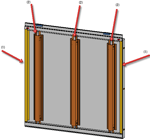
ALUCOBOND® tray panel - (1) Stiffener profiles at edges of panel; (2) Stiffener profiles on ("inside") panel
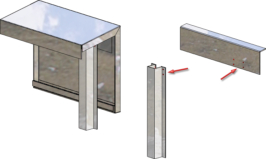
ALUCOBOND® Tray panel SZ 20 - Left: Double folding; Right: Window connection with L-profile
Please note the following for ALUCOBOND® Tray panels SZ-20 - depending on the settings during insertion:
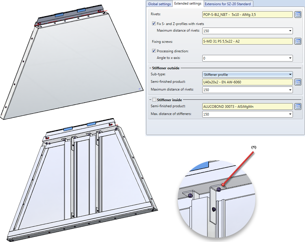
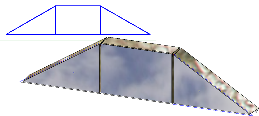
Example of a trapezoidal ALUCOBOND®Tray panel SZ-20, (1) No bores are created here!
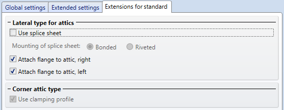
Extensions for SZ-20 Standard
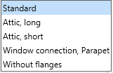
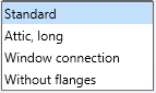
On this tab you can specify the type of the lateral flanges for the connection types Attic, long / Attic, short. Also, you can specify here whether corner attics are to be created with or without clamping profile. Furthermore, you can specify the depth of the tray panel here.
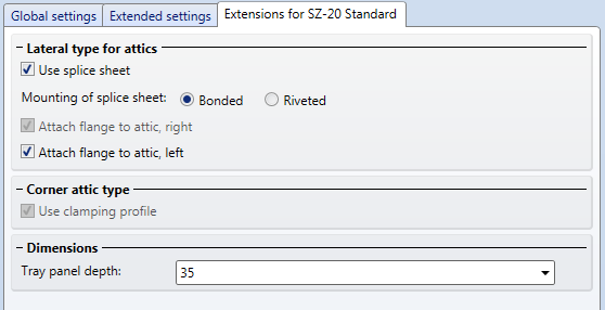
The connection between splice sheet and tray panel can be a bonded or a riveted one. The rivets will be inserted on one attic side only, at a 50 mm distance to the edge.
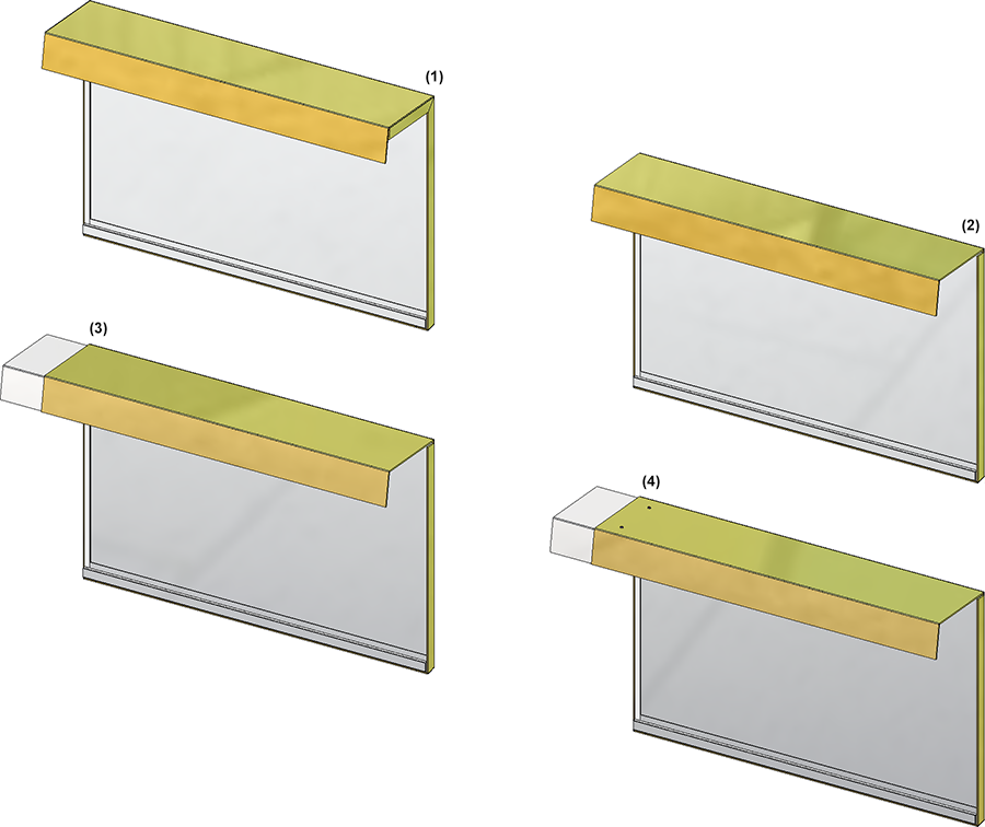
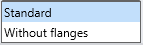
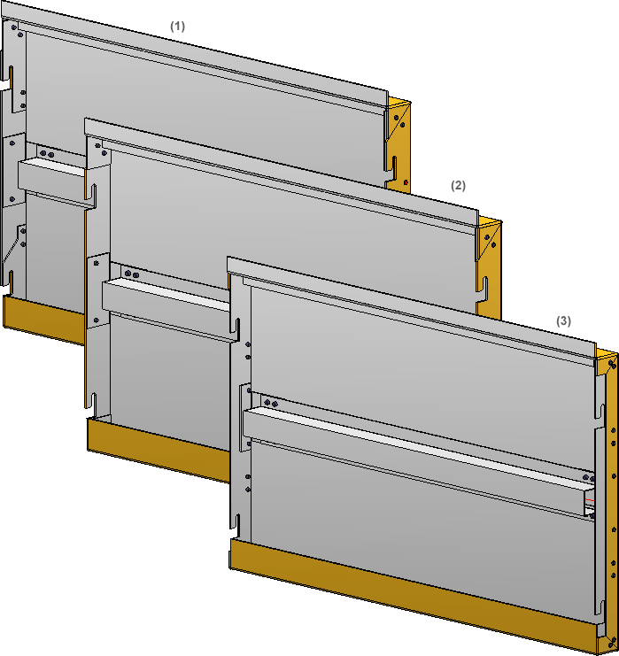
(1) Standard; (2) Without side flanges; (3) Splice sheet, bonded; (4) Splice sheet, riveted
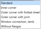
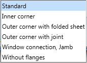
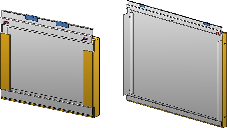
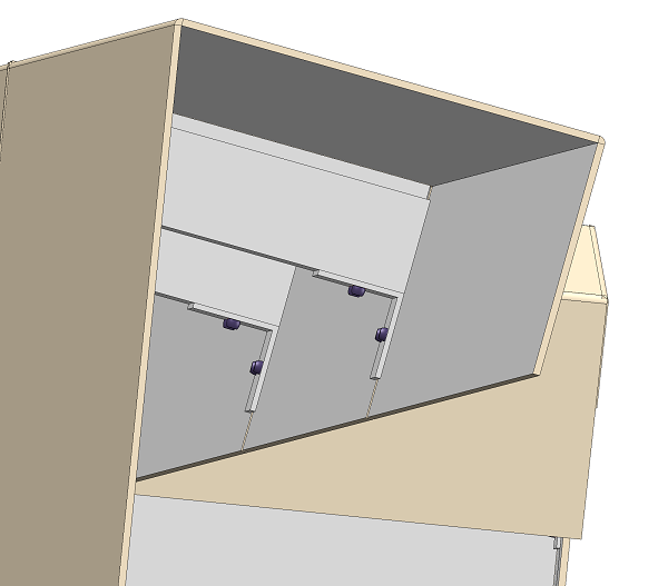
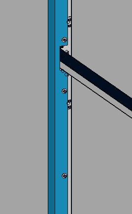
The image below shows a SZ-20 tray panel. Horizontal section: Connection, top. Attic, long; Vertical section: Connection, right. Outer corner with folded sheet. The left tray panel has been created with splice sheet and clamping profile, the right one without these elements.
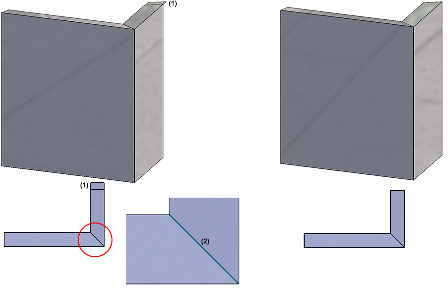
(1) Splice sheet, (2) Corner attic with clamping profile
For SZ 20 element installations, a matching profile for a sub-structure is available. -Elementverlegungen steht auch ein passendes Profil für eine Unterkonstruktion zur Verfügung.
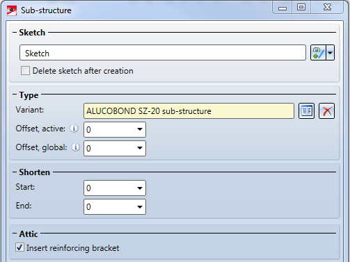
Die Option Verstärkungswinkel einbauen hat dann einen Effekt, wenn die Unterkonstruktion über die Funktion Verbindung mit einer Elementverlegung verbunden wird, die Elemente mit Attika-Anschluss enthält. In dem Falle wird die Unterkonstruktion über Winkel mit der hinteren Attika-Lasche verbunden und vernietet:
The processings on the tray panels will be created through the mounting to the sub-structure.
Wie bei den SZ20-Kassetten stehen auch für eingehängte ALUCOBOND Kassetten legen Sie auf den Registerkarten (mit Zubehör) stehen im Dialogfenster drei Registerkarten mit Einstellungsmöglichkeiten zur Verfügung.
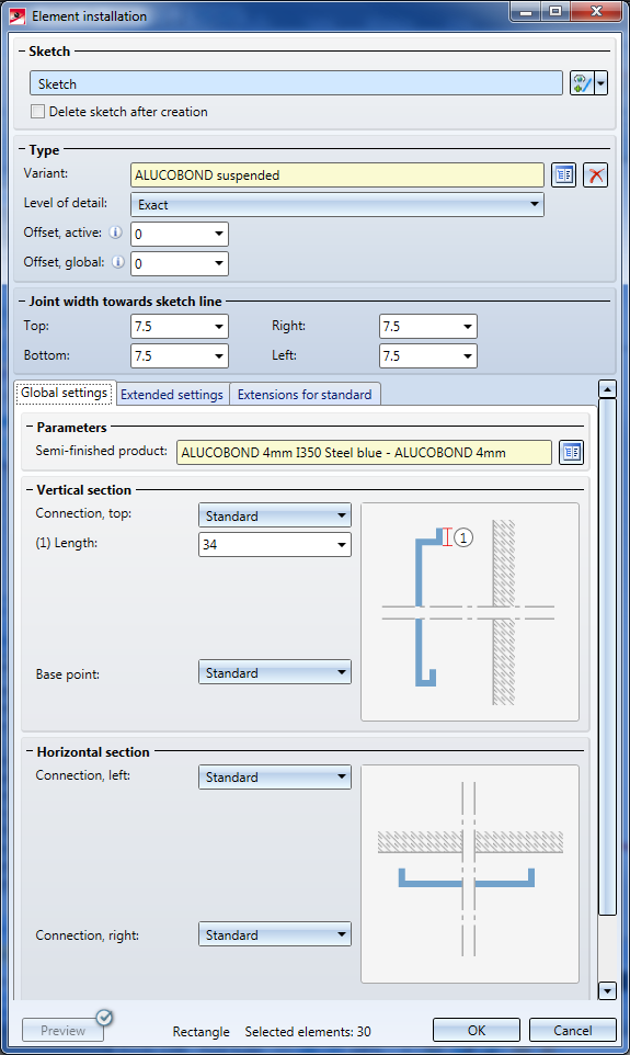
Global settings
Hier wählen Sie das gewünschte Halbzeug sowie die Parameter für den Anschluss oben, am Fußpunkt, links und rechts.
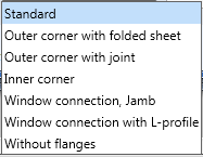
Possible connection options:
|
Horizontal section |
|||
|
Top |
|
Base point |
|
|
Vertical section |
|||
|
Left |
|
Right |
|
Depending on the chosen connection type, further input fields may be displayed.
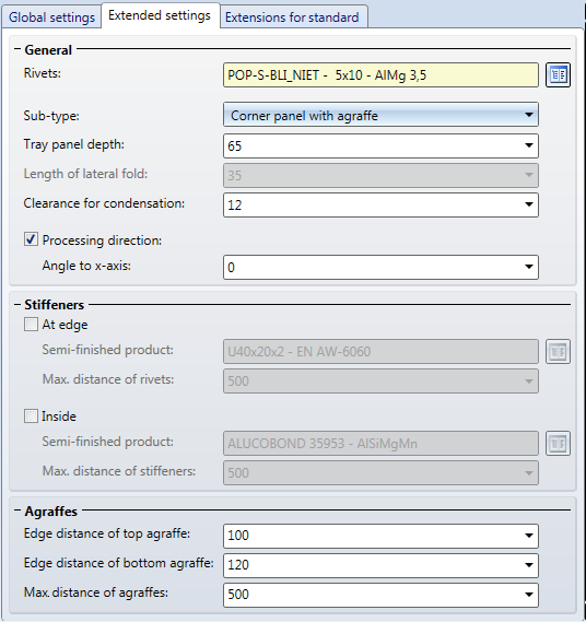
Extended settings
On this tab you can specify further settings such as:
Sub-type: (1) Corner panel with agraffe; (2) Corner panel without agraffe; (3) Sheet insert - with stiffeners at edges and in the middle
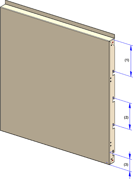
(1) Edge distance of top agraffe; (2) Distance between 2 agraffes; (3) Edge distance of bottom agraffe
Extensions for standard
On this tab you can find further options for attic connections, similar to the options for the SZ-20 tray panels.
Notes on agraffes
The height and width of the agraffes can be preset in the table Agraffes of the catalogue Factory standards > Bore patterns. In this table two data records have been predefined that you can use as a basis for further sub-types. 
Please note that only agraffes based on the part ISD_AGRAFFE_01-Y.KRA, i.e. agraffes of the Type Y-, are allowed here.
A new sub-structure of the type ALUCOBOND suspended, sub-structure is now available. This part can be mounted to element installations of the type ALUCOBOND, suspended by means of the Connection function; recesses for the suspension will be created automatically in the process.

Element Installation • Catalogue Editor
|
© Copyright 1994-2019, ISD Software und Systeme GmbH |