 If you want the installation to be possible on rectangular sketch areas, you need to additionally use the variants i_l and i_h!
Project: HiCAD Dach/Wand/Fassade
Installation elements can also be defined variably. For this purpose, the i_nr variable can be used. A number of corners n will be assigned to this variable. This allows an installing of this element on sketch areas with 3 to up to n corners.
In addition, the variables of the 4th, 5th and nth corner point must contain a query for the number of corners of the sketch area, namely, as follows:
|
Corner point |
Variable |
Effect |
|---|---|---|
|
4th corner point |
i_nr>3?x3:x0 i_nry>3?y3:y0 |
If the selected sketch area has 3 corners, the 4th corner point of the installation element will be placed into the 1st corner point, i.e. a triangle will be created. |
|
5th corner point |
i_nr>4?x4:x0 i_nr>4?y4:y0 |
If the selected sketch area has 4 corners, the 5th corner point of the installation element will be places in the 1st corner point, i.e. a rectangle will be created. |
|
.... |
..... |
|
|
nth corner point |
i_nr>n-1?xn-1:x0 i_nr>n-1?yn-1:y0 |
If the selected sketch area has n-1 corners, the "nth corner point -1" will be placed into the 1st corner point, i.e. a "n-1-gon" will be created. Eck. |
If you want the installation to be possible on rectangular sketch areas, you need to additionally use the variants i_l and i_h!
An example:
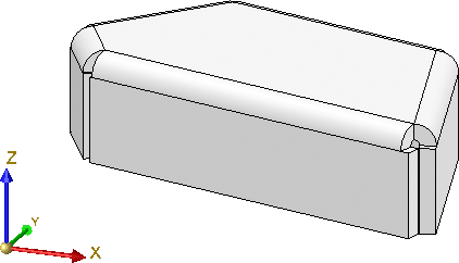
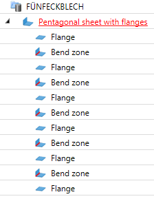
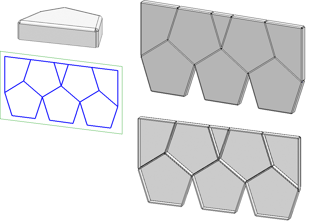
Let us assume that you want to create a pentagonal sheet with flanges as an installation element. This sheet is to be adjusted to - and subsequently installed on - triangular and rectangular areas.
The basic procedure is quite similar to that for the example with the triangular sheet. However, the variable i_nr will be used here.

 to create a new sketch.
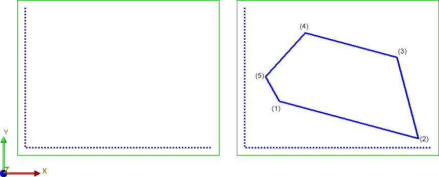
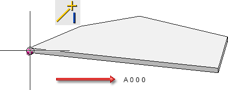
  to draw two lines as shown below - one parallel to the Y-axis, the other one parallel to the X-axis. You will need these lines as an auxiliary geometry for parameterization, i.e. they virtually symbolize the coordinate system for the corner points of the pentagonal shape that you want to draw.
  > Auxiliary geometry
  and select the two lines. They will then be displayed as dashed lines.
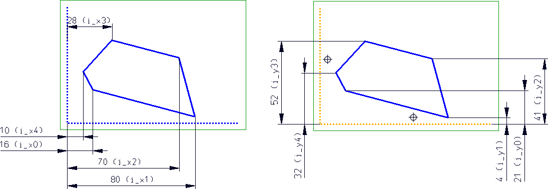
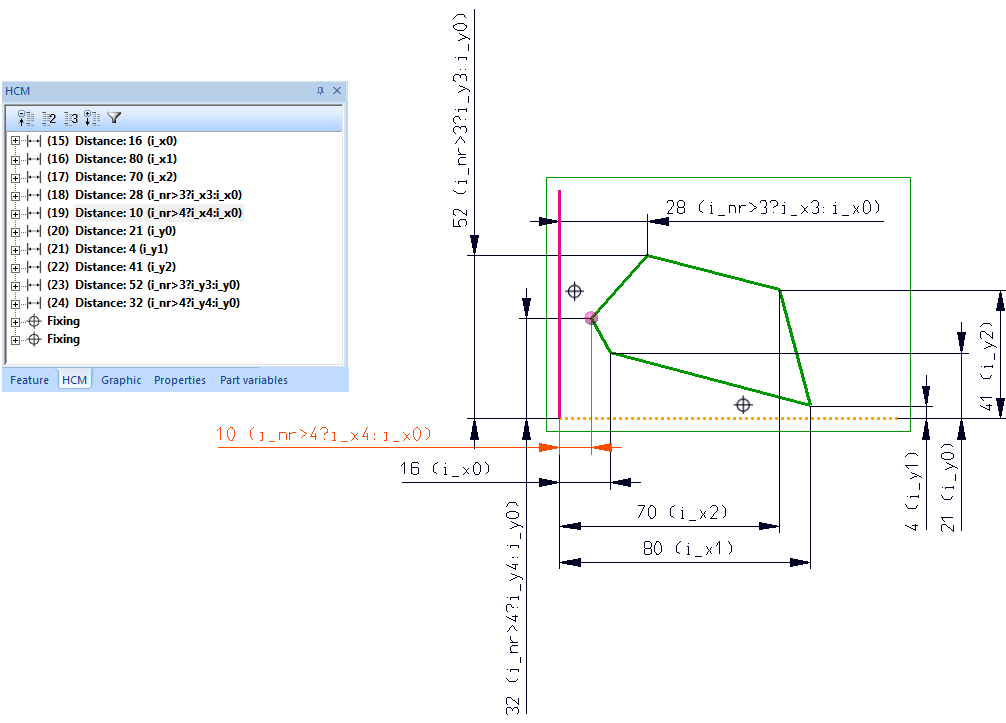
 and specify the distance constraints of the 3 corners to the vertical auxiliary line (HCM scaling = Scale complete sketch). Choose i_x0 and i_x1 to i_x4 as variables.
  and select the two lines of the auxiliary geometry.
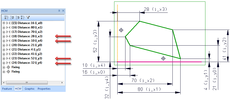
For this to happen, the constraints for the corner points must be changed in the HCM log (double click) in the following way:
|
|
Replace with |
|---|---|
|
i_x3 |
i_nr>3?i_x3:i_x0 |
|
i_y3 |
i_nr>3?i_y3:i_y0 |
|
i_x4 |
i_nr>4?i_x4:i_x0 |
|
i_y4 |
i_nr>4?i_y4:i_y0 |
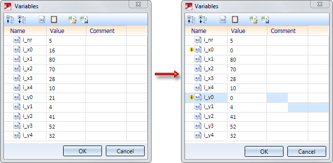
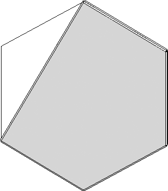
Since the variable i_nr has not been defined yet, it will be queried. In this example, select the value 5.
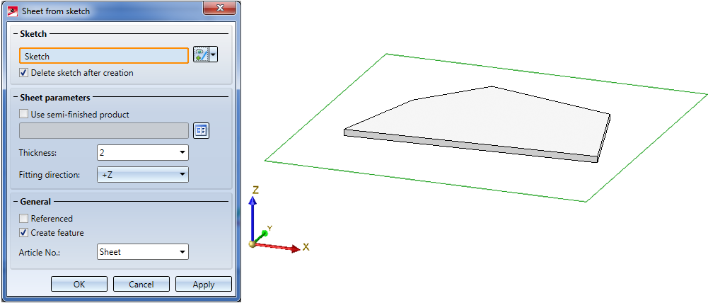
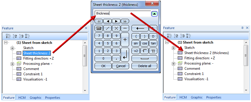
 , select the sketch, enter the sheet thickness and close the dialogue window with OK.
 .
.
The Fitting CS determines the insertion direction of a part in space. It consists of 3 special points:
If a 3-D part to which a Fitting CS has been assigned is loaded into a new model drawing, the points of the Fitting CS will be placed into the World CS. In this way the insertion direction in space will be determined.
The definition of a Fitting CS is of particular importance if the installation element is an assembly. If this assembly is saved to the Element installation catalogue while no Fitting CS is assigned to it, the Part CS will be used as Fitting CS when the part is inserted. However, this may lead to unwanted results during the installing process.
Please note:
Not all assemblies have automatically a Feature log. For instance, this applies to assemblies that have been created with the Form assembly function, or via New > Assembly. If you assign a Fitting CS to these assemblies, no corresponding Feature log entry will be generated. To achieve this, you must assign a so-called body creation feature to the assembly. To do this, right-click on the Feature window of the assembly and select the corresponding function in the context menu. After this, the definition of the Fitting CS will be entered as a Feature here, too.
Continuation of the example:
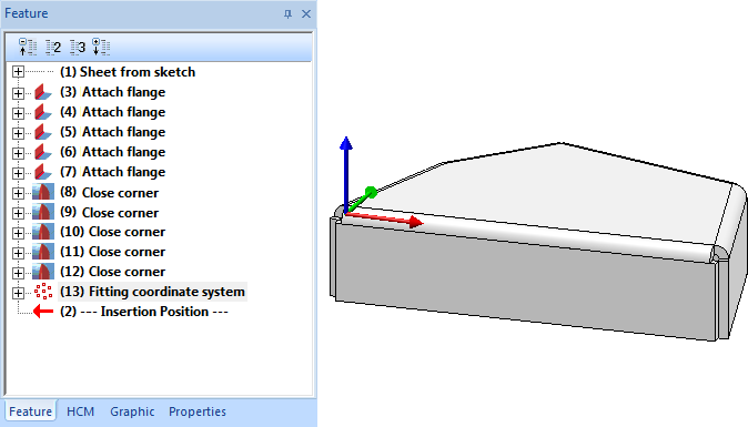
As already mentioned, the sheet in this example is to be inserted in such a way that the first corner (i_x0, i_y0) lies in the bottom left corner of the selected sketch area. Therefore, a Fitting CS must be defined for the Sheet Metal main part.
Choose Drawing > Others > World CS > Define Fitting CS  and proceed as follows:
(1) New origin of coordinate system is the bottom left corner of the pentagonal sheet (i_xo,i_yo), i.e. Absolute 0 0 0.
(2) Point on X-axis: R (Relative) 200 0 0
(3) Point on y-axis: R (Relative) 0 200 0
The Fitting CS will be entered into the Feature log.
The installation element has been completed and can now be saved to the catalogue.
To be able to directly create a preview image for the catalogue, switch to a non-shaded view beforehand.
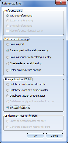
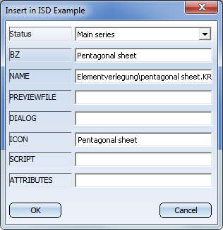
To save an installation element to the catalogue, choose Drawing > Save/Reference > Part..  and use the settings shown below. Please make sure that the Sheet Metal main part is active!
In this example the folder Installation elements and the table Example have been selected. In the The "Element Installation" Catalogue chapter is is explained how tables for element installation must be composed.
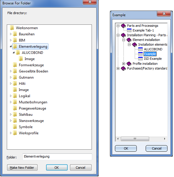
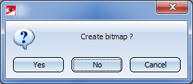
... click Yes. This creates a preview image of the data record Pentagonal sheet from sketch, namely, in the sub-folder image of the folder selected for the .KRA file, i.e. for instance, Kataloge\Werksnormen\Elementverlegung\image
.
Please note:

Customer-specific Installation Elements • Catalogue Editor
|
© Copyright 1994-2019, ISD Software und Systeme GmbH |