Project: HiCAD Plant Engineering
Plant Engineering > Isometry / Pipe Spool Drawing > Isometry settings
Plant Engineering > Isometry / Pipe Spool Drawing > Pipe spool drawing settings 
Isometry + Pipe spool drawing > Settings 
 The following description refers to isometries and pipe spool drawings.
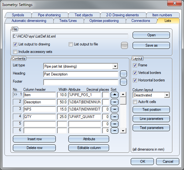
The Lists tab enables you to specify the content and layout of lists. HiCAD creates and then inserts these lists in isometric pipeline drawings. There are three types of lists: Pipe part lists, Length lists and Weld seam lists. The lists can be output directly to the drawing or to a file.
The tab consists of three areas:

This area displays the name of the definition file for the isometric drawing of the pipeline. HiCAD displays file data in the Content and Layout areas, where you can edit it. You can select the type of list to which the current settings should apply from the List type selection list.
Click the Open button to load another definition file. Select Save as... to save the (revised) settings to the current or another definition file.
You can output the files directly to the drawing or to a file by activating the appropriate checkbox. If you choose to output the list to a file, click  and select the desired file format, i.e. XLS, TXT or CSV.
If you want the accessory parts to be included in the the Pipe part list, activate the appropriate checkbox. All accessory parts fitted in the layout plan will then be handled and itemised like "normal" parts.
The options available in this field determine the appearance of the list, i.e.
In the Configuration Editor, at Plant Engineering > Isometry and Pipe spool drawing > BOM layout > Column layout definitions you can define the column layouts to be shared by the BOMs. Automatically calculated column widths are also supported.
The underlying mechanism for a shared column layout for several BOMs can be explained as follows:
If you assign the same column layout to several BOMs, column widths will be calculated in such a way that the contents of all BOMs will be considered. In this way it is, for example, also possible to only align the pipe part list and the length list to each other, while having an independent representation for the connection list.
If you selected a column layout for one BOM, you can then only specify a number for the individual columns, instead of the width (as was previously the case). This number refers to a column of the column layout
If you want to use a particular Column layout, select it from the same-named listbox. The Auto-fit cells checkbox will then be deactivated.
If you want to work without column layouts, select the Deactivated option from the list. You can then activate the  Auto-fit cells checkbox in order to automatically adjust the column widths to the corresponding text lengths. If the checkbox is deactivated, you can specify the column width yourself. In this case, please make sure that the widths are actually sufficient for the corresponding texts lengths.
|
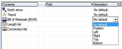
Notes on BOM alignment Bills of materials can be aligned automatically (Left/Right/Top/Bottom) or manually (No default/Position) on the 2-D Drawing elements tab of the Settings dialogue window for isometries or pipe spool drawings .
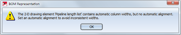
For manual alignment HiCAD will assume that the BOM has been created with fixed column widths. Accordingly, such a BOM will not obtain any automatic column widths, but the fixed widths determined in the table definition beneath Contents. If automatic column widths are used for BOM creation, and the manual alignment has been chosen in the settings for isometries or pipe spool drawings, the following message will be displayed:
After confirming with OK, the BOM BOM will be placed on the right by default. Please note that editing the BOM may lead to unwanted results in such cases. Therefore, you should either choose the automatic alignment, or use a table definition without automatic column widths. |
More details on how to configure column layouts can be found in the Configuration of BOM Layouts (PE/Iso) topic.
This area enables you to specify type and contents of respective list.
Six different list types are available:
The settings for each list type can be saved via a definition file (with the file extension ild.XML). This enables you to choose between different configurations for an output to a drawing or to a file. You can, for example, output additional columns in the created file, which would not be possible for an output to a drawing owing to lack of space.
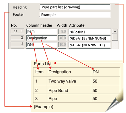
Our example below refers to the settings for the Pipe part list. The table in the Contents area determines content and width of list columns (without column layout), or the number of a column layout (when working with column layouts), i.e. the column header and an attribute placeholder. The attribute placeholder will be replaced by the corresponding attribute value when the list is generated. For each (numerical) column you can set the desired number of decimal places.
The text in the Heading input field will be written above the list, the text in the Footer input field below the list. In You can also use attributes of the pipeline in the header or footer. To do this, click the corresponding  symbol. The Attribute selection dialogue window is displayed, enabling you to choose the desired attributes.
The contents of the table can be edited with the following buttons:
|
Insert row |
This option inserts an empty row next to the active row. The active row is indicated by „>>“ in the first column. Click the input field to activate a row. |
|
Delete row |
This option deletes the active row. |
|
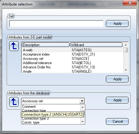
This option enables you to process the attribute entry for the active row. Set This field initially displays the current attribute entry of the currently selected row in the List tab. You can change the entry by using a set consisting of texts and attribute wildcards (placeholders). Enter the required text and select the part or database attributes from the listboxes below. Click the
Attributes from 3-D part model In this area the attributes of the 3-D part model are offered for selection. HiCAD takes these data directly from the drawing data memory. To copy the desired attribute placeholder directly and without any changes to the active list row, select it from the listbox and click the Apply button. If you want to copy the attribute into the Set field, click the
Attributes from database In this area the master data of the part are offered for selection. These data are read from the HELiOS database. To copy the desired attribute placeholder directly and without any changes to the active list row, select it from the list box and click the Apply button. If you want to copy the attribute into the Set field, click the Click Cancel to close the dialogue window without applying any changes. |
|
|
Editable column |
The BOMs of isometries and pipe spool drawings are generated from data that is provided by the pipeline itself. Such a BOM can be edited after its generation, and the changes can be saved in the BOM. If the pipe spool drawing or the isometry is now re-generated, e.g. because the pipeline has been changed, all BOMs will be re-generated as well. In older versions (before HiCAD 2014 SP1), all data that was entered manually via the editing functions was then lost. In the Lists tab of the Settings dialogue for pipe spool drawings you have now the option to define for individual columns of a BOM that their values can be filled in manually afterwards. For this you use the Editable column button. When you apply this behaviour to a column, an attribute in the form of %USR(SCHLUESSEL) will be entered there. The key in brackets will be generated in a random manner. If you mark a column already containing attribute keys as editable, HiCAD will ask you whether you really want to replace the current attribute key. If this is the case, confirm the security prompt with Yes. The current attribute key will then be replaced with the %USR key. The character string USR serves as a marking, indicating that the contents of the column will be specified by the user, , while the key identifies the data. If the BOM will be temporarily removed, or will be re-generated, the data that were previously defined for this key will be re-entered here. The data will be saved in all pipe parts from which the row content the BOM was generated, i.e. in a BOM with part item numbers the data will be saved in all pipe parts to which the same item number had been assigned. This means that the USR keys behave exactly as if they refer to pipe properties. In particular, they are copied and deleted together with the parts to which they belong. The Reset isometry and pipe spool drawing data function now also removes the entered BOM data from the parts. Although the keys are generated in a random manner, but can also be defined by the user if desired, e.g. %USR(Notes). Allowed are alphanumerical characters and underlines. This makes sense, for example, if you want the data you have entered in the BOMs of the pipe spool drawing to be available in the BOMs of the isometry as well, by using the same key there. Please note however that you should not use the same key for different BOM types, as the data of the last generated BOM will then overwrite the data of the previous BOM! When you close the Lists tab, or save the settings, HiCAD will check whether the keys are appropriately unambiguous. If this not the case, a warning message will be displayed.
Each time when you edit a an isometry or pipe spool drawing BOM, HiCAD will also check for each BOM row whether the parts from which they were created still exist. If this is not the case, a warning message will be displayed.
|
Normally, the BOMs of the isometry are sorted according to the assigned item numbers. If you want a different sorting, click the desired button below Sort....
The contents of each column can be sorted in ascending  or descending
  order, or not at all
  . The first columns have priority over the columns that follow, the sorting of which is only relevant if the order has not already been defined by previous columns.
Please note:

Settings (PE/Iso) • Isometry and Pipe Spool Drawing (PE/Iso) • Isometry and Pipe Spool Drawing Functions for the Layout Plan (PE) • Special Attributes in Lists/Text Objects (PE/Iso) • Configuration of BOM Layouts (PE/Iso)
|
© Copyright 1994-2019, ISD Software und Systeme GmbH |

 icon to copy the selected attribute into the set. Then click the Apply button to copy the content of the Set input field over into the selected row as a new attribute entry.