Project: HiCAD Plant Engineering
In the Configuration Editor you can specify various BOM layouts in isometries / pipe spool drawings.
You can find these setting options at

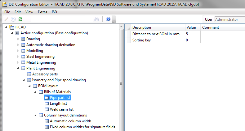
At Plant Engineering > Isometry and pipe spool drawing > BOM layout > BOMs you can specify the distance below a BOM to the next BOM, separately for
If you want to place several BOMs one below the other, you can define the distances below the BOMs, as well as their position by assigning a sorting key to each BOM. In previous versions the order of the BOMs could only be changed by means of adding and deleting. The sorting key makes sorting much more convenient.
At Plant Engineering > Isometry and Pipe spool drawing > BOM layout > Column layout definitions you can define the column layouts to be shared by the BOMs. Automatically calculated column widths are also supported.
The settings specified for Fixed column width for signature fields will be used if you choose the column layout Signatures on the Lists tab of the isometry settings dialogue. The settings for Automatic column width will apply if you have chosen the column layout Automatic.
The image below shows the setting options for a concrete column layout in which the columns 4 and 5 have been assigned a fixed width of 40 mm. The width of the other columns will be determined automatically, based on the BOM contents.
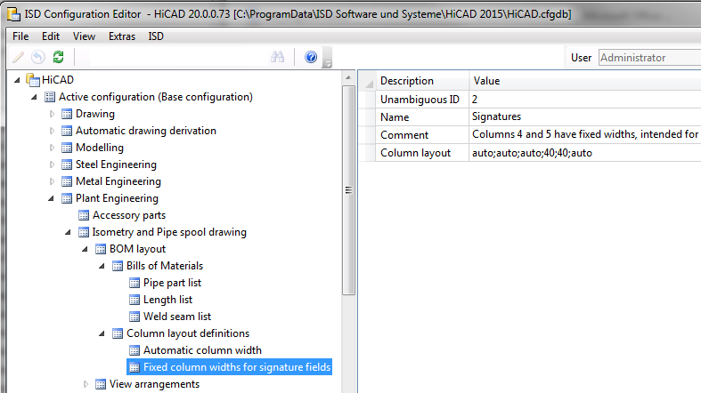
The parameters are as follows:
| Unambiguous ID |
This is an unambiguous number that needs to be different for each layout. HiCAD uses this ID to memorize the currently selected layout. |
| Name |
The name will be used in the Column layout listbox on the Lists tab of the isometry settings dialogue window. |
| Comment |
This texts provides a detailed description of the column layout and will be shown (together with the name) as tooltip, when you move the cursor over the entry in the Column layout listbox. |
| Column layout |
The most important property of such a layout definition is the Column layout parameter. This is a list of entries separated by semicolons. Each entry can either be a number or the keyword auto. The number directly specifies the column width in mm. The last entry specifies the width for all following columns. A layout providing an automatically calculated width for each column, thus only contains the keyword auto once. |
On the Lists tab of the isometry settings dialogue window, you can specify the column layout to be used. In the screenshot below you can see the Column layout list box on the right hand side of the dialogue:
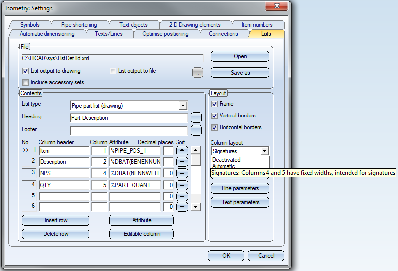
The selected column layout for the pipe part list has the name Signatures (third entry in the expanded listbox). When you move the cursor over an item in the listbox, the comment for this entry will be displayed as a tooltip.
The underlying mechanism for a shared column layout for several BOMs can be explained as follows:
In the above screenshot, references are made to the columns 1, 2, 4 and 5. These column numbers always refer to the first column to be used in the column layout: In the above example, the BOM column with the header Description spans two columns of the column layout (namely, the columns with the numbers 2 and 3). The result looks as follows:
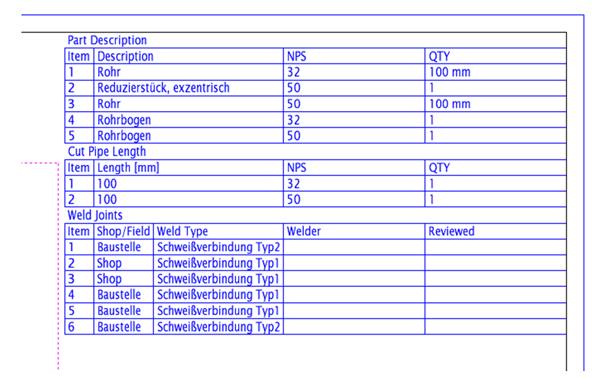
The Description column of the Part Description BOM spans two columns. The total width is determined by the widths of columns 2 and 3 of the Weld Joints BOM. The columns of the last mentioned BOM with the headings Welder and Reviewed each have a width of 40 mm breit, since they refer to column numbers 4 and 5 of the Signatures column layout.

Settings (PE/Iso) • Isometry and Pipe Spool Drawing (PE/Iso) • Isometry / Pipe Spool Drawing Functions for the Layout Plan
|
© Copyright 1994-2019, ISD Software und Systeme GmbH |