Project: HiCAD Plant Engineering
The functions for the generation and processing of of Isometries and Pipe spool drawings are available in an optionally available, additional module which requires a separate licensing and can only be used in conjunction with the HiCAD Plant Engineering module.
The available isometry and pipe spool drawing functions differ for separate isometry and pipe spool drawings and the isometries/pipe spool drawings in the sheet area of a layout plan:
The isometry and pipe spool drawing functions in the sheet area of a layout plan can be found in the Isometry / Pipe Spool Drawing function group of the Plant Engineering tab.
The functions for separate isometry and pipe spool drawings can be found on the Isometry + Pipe spool drawing tab.
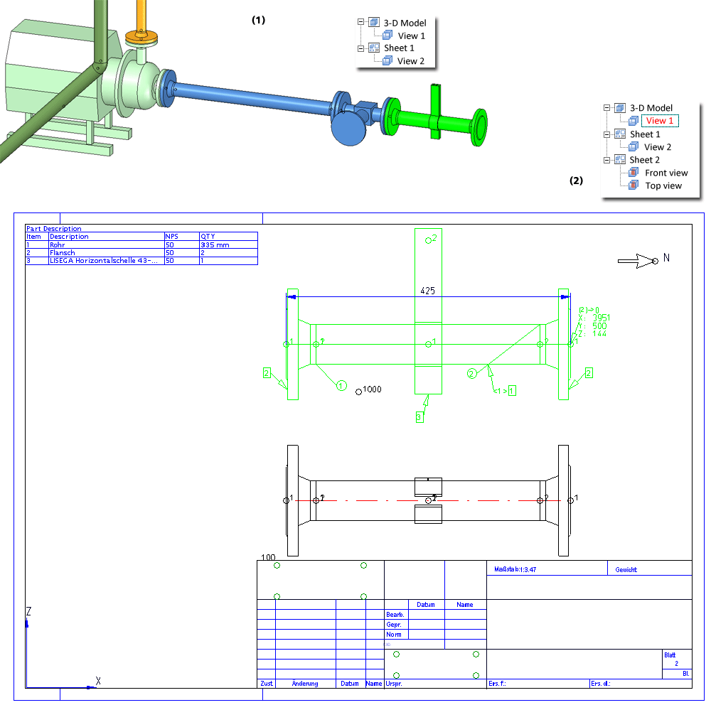
Pipeline isometry
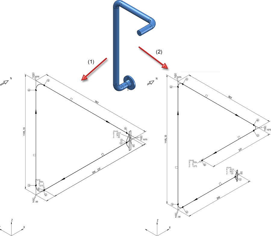
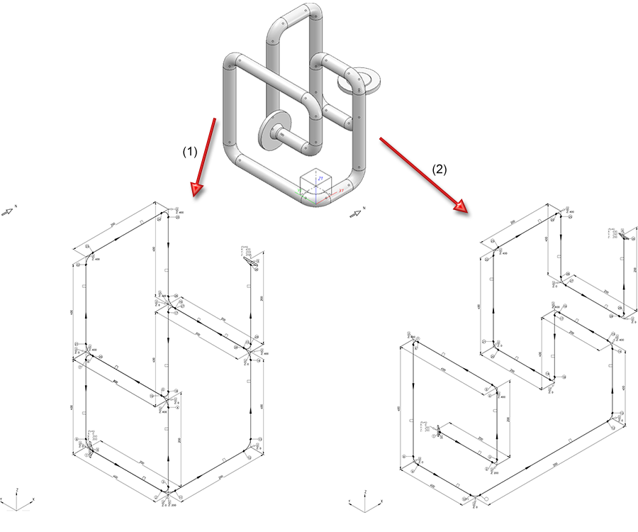
For each pipeline in a 3-D layout plan a so-called Isometry can be generated, which is created as a scale-dependent, special view of the 3-D model.
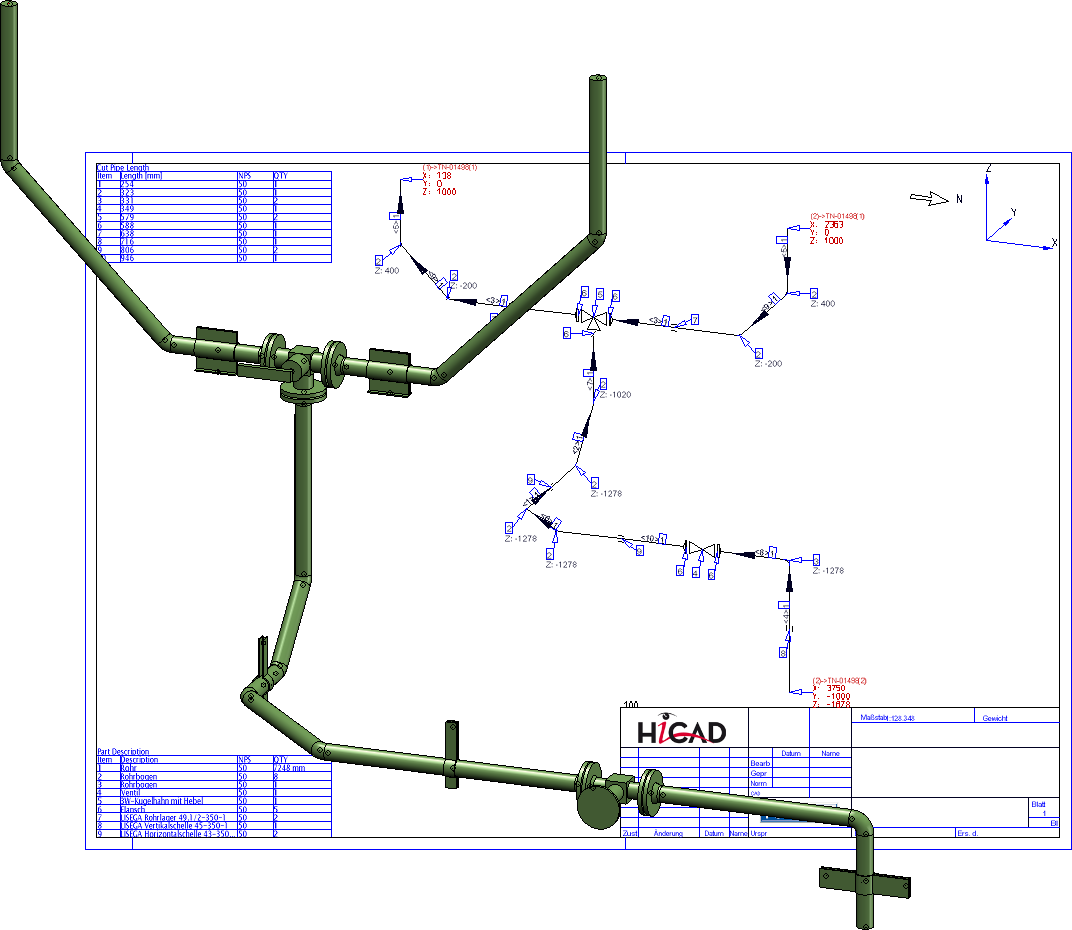
In contrast to a pipeline isometry, a so-called pipe spool drawing is generated from the active view of a pipeline. The available elements are:
The pipe spool drawing considers the visibility of the individual pipe parts, e.g. for dimensioning or in the BOMs.
 Please note:
If you do not want to use the new drawing layout of HiCAD 2015, you can switch it off in the Configuration Editor: Select Plant Engineering > Isometry and Pipe spool drawing and deactivate the Avoid intersections by means of pipe shortening checkbox.


Isometry and Pipe Spool Drawing Function for Separate Drawings (Iso) •Isometry and Pipe Spool Drawing Functions for the Layout Plan (PE) • Plant Engineering Functions
|
© Copyright 1994-2019, ISD Software und Systeme GmbH |