> Insert weld symbol
Project: HiCAD 3-D
3-D Standard > Standard Parts > Weld > Insert weld symbol
Weld seams indicate a welded connection of two edges of a workpiece. You can use this function to configure weld symbols after weld seam insertion as well as the symbolic representation of the weld seams (acc. to DIN EN ISO 2553). The representation consists of an arrow line, a reference line and further information on geometry, creation, quality and inspection of the weld seam, e.g.:
Depending on the type of the weld seam, other, additional symbols (e.g. flat, domed etc.) and supplementary information can be selected.
Symbolic representations are configured via the settings in the Weld symbol dialogue window. Use the  and
and  icons to switch between simple and extended display of the dialogue window.
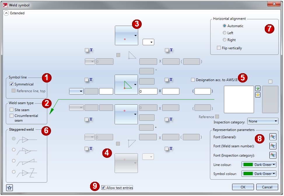
Dialogue window for weld seams (extended settings)
(1) Symbol line
Activate the appropriate checkboxes to determine the type of the reference line. If the Symmetrical checkbox is active, the annotation is created with a solid line. If the Symmetrical checkbox is not active, the annotation is created with a dashed reference line at the top or bottom.
|
|
Symmetrical |
|
|
|
|
Reference line, top |
|
|
|

|
Symmetrical Reference line, top |
|
|
(2) Weld seam type
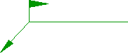
In this field you specify the type of the seam type. Site seams are identified by a flag-like symbol at the start of the reference line, Circumferential seams by a circle symbol.
|
|
Site seam |
|
|
|
|
Circumferential seam |
|
|
(3) Symbolic representation on reference side
In this area you can select the symbolic representation on the reference side. Select the desired weld symbol. Depending on the type of the selected symbol, other input fields and symbol selection fields will be active. For example, a fillet weld can be further specified (flat, domed etc.).
Use the selection box next to the symbol selection to choose a surface treatment specification. The default setting for the selection options have been pre-defined by the ISD in the Configuration Editor, at Modelling > Weld seams > DIALOG.
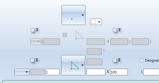
Example of a domed fillet weld
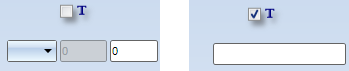
Activate the  checkbox to convert the input field beneath it into a text input field. This checkbox will only be shown if you had activated the Allow text entries checkbox at the bottom of the dialogue window beforehand.
Designations for interrupted weld seams can be created according to DIN or AWS / JIS (American Welding Society / Japanese Industrial Standard). The default setting is DIN. If you want a designation according to AWS / JIS, activate the corresponding checkbox.
|
Designation acc. to DIN |
Designation acc. to AWS/JIS |
|---|---|
|
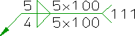
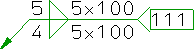
Number of seam segments x Nominal length of single seam (offsets between single seams) |
Number x Nominal length of single seam - Segmentation Segmentation = Distance between midpoints of neighbouring single seams or, somewhat simplified, Single weld length + Offset |
|
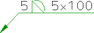
Example: 10x20(5) |
Example: 10x20-25 |
Depending on the selected seam type, info texts for the individual input fields will be displayed if you move the cursor over them.
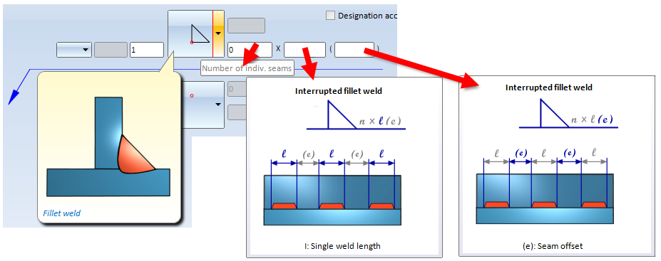
Input fields for fillet weld: Info texts
(4) Symbolic representation on opposite side
In this area you can select the symbolic representation on the opposite side. You proceed in the same way as with the reference side.
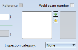
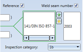
(5) Tail, Details, Reference, Weld seam number, Inspection category
 .....
..... 
You can enter details about processes, quality levels, welding positions, additional materials etc. in the left box. The reference line will then be created with a tail.
If the Reference checkbox is additionally active, the text appears in a frame.
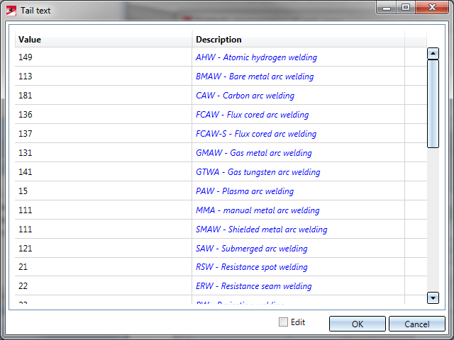
Click the  icon to add entered texts to your Favourites. You use the
  icon to copy texts from your Favourites. You can then edit texts that have been saved as Favourites. Several tail texts have been predefined by the ISD in the Configuration Editor, at Modelling > Weld seams > Dialogue.
If you activated the Weld seam number checkbox, you can specify a weld seam number in the field below for clear identification of a weld seam in your drawing. The next free item number for weld seams will be suggested to you. The weld seam number will also be considered in weld seam lists.
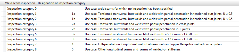
In the Inspection category list box you can select the test procedure according to DIN EN 1090. The inspection categories have been predefined in the Configuration Editor, at ... > Modelling > Weld seams. They are evaluated in weld seam test protocols.
(6) Staggered weld
This area is only active if a staggered weld has been selected. You can further specify the weld by activating the appropriate radio buttons.

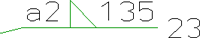
Example of an offset, interrupted fillet weld, seam thickness 5 on the reference side and 4 on the opposite side.
(7) Horizontal alignment
In this area you can change the alignment of the weld seam. The Automatic option is preset by default, i.e. HiCAD determines the alignment automatically, depending on the corresponding fitting situation. Alternatively, you can change the alignment. If you select left / right, the reference line is located to the left / right of the arrow line. In addition, you have the option to reverse the representation vertically, i.e. the annotations of the reference side and the opposite side are swapped.
(8) Representation parameters (colour, font) of the annotation
Here you specify the line colour of the weld seam symbols and the text parameters of the annotation  The text parameters for the weld seam numbers and the inspection category can be specified independently from other texts.
After completion of your settings, exit the window with OK.
Specify the start point of the arrow line, either by selecting a point or by identifying an edge. In the latter case the start point is located in the perpendicular from the identification point to the edge.
Now specify the start point of the reference line.
(9) Allow text entries
If required, you can also use individual, user-defined texts instead of pre-defined texts for the various entries. Do do this, you need to activate the Allow text entries checkbox. Another checkbox  will then appear next to the various specifications for weld seam annotations. By activating this checkbox you unlock the corresponding input area for individual text entries.
After specifying all settings, exit the window with OK.
Define the start point of the arrow line, either by a point specification or by identification of an edge. In the latter case, the start point is located in the perpendicular from the identification point to the edge.
Then, identify the start point of the reference line.
 Please note:
 symbol at the bottom left of the window. The saving of Favourites does not include the representation parameters. More about Favourites management can be found in the Manage Favourites topic in the HiCAD Basics Help. > ....

Standard Parts (3-D) • Standard Parts, Boltings, Rivetings, Weld Seams (3-D) • Insert Weld Seam (3-D) • Process Weld Symbol (3-D)
|
© Copyright 1994-2019, ISD Software und Systeme GmbH |