Project: HiCAD 3-D
3-D Standard > Standard Parts > Insert new weld seam
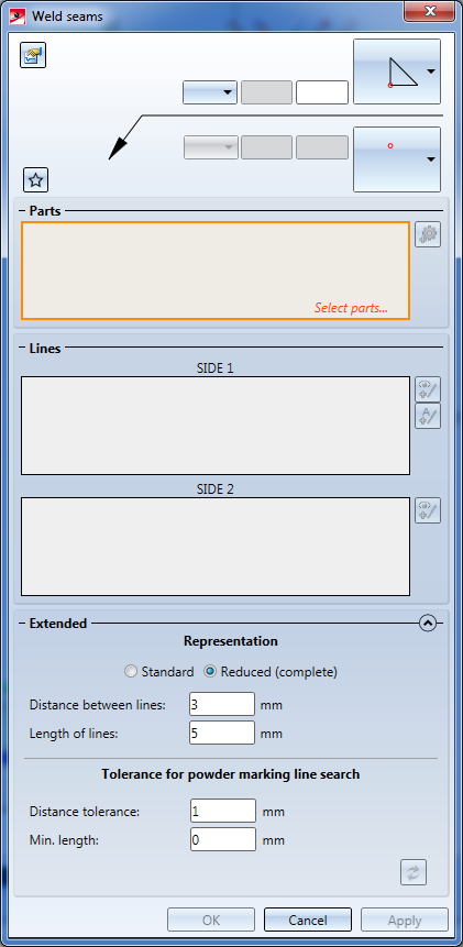
Use this function to insert new weld seams. The function also offers double-sided weld seams and K-seams.
When you call this function, the Weld seam dialogue window will be displayed, and HiCAD will prompt you to select the parts to be welded together. The parts do not need to be in contact with each other.
The settings specified in the dialogue window can be saved as Favourites and reused at any time. To do this, click the  symbol. More about Favourites management can be found in the Manage Favourites topic in the HiCAD Basics Help.
Select parts
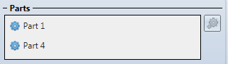
Identify the part to be welded on, and then the part to which the welded connection is to be made ("target part").
The identified part are entered into the part list of the dialogue window.
If you want to remove parts from the part list, right-click the part and select Delete. To add a new part to the list, click the Select part  icon and select the desired part in the drawing or in the ICN.
Detect powder marking lines - Side 1 / 2
After selection of the parts to be welded together, HiCAD automatically detects the powder marking lines for the welding (if possible) and highlights them in the drawing, taking the specified Tolerance for powder marking line search into account.
If you want to take over all highlighted powder marking lines for one-sided seams (Side 1), click the Auto  icon. The corresponding edges are taken over into the edge list for Side 1 of the dialogue window. A selection for Side 2 will then no longer be possible.
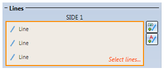
If you want to take over only some of the edges, click the Individual  icon and identify the desired edges with the cursor. The edges will be taken over into the edge list of the dialogue window. During edge selection you can right-click to open a context menu:
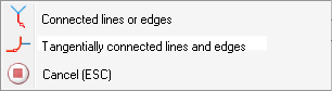
To end the edge selection, select Cancel (ESC), or press the middle mouse button if the context menu is not open.
You have then the option to select the edges for Side 2 for double-sided weld seams.
To remove entries from Lines lists, right-click on the corresponding row and select Delete in the context menu.
In this case an appropriate error message will be issued. If desired, change the value for Distance tolerance and Minimum length (both > 0 and < 100).
 Use the
  and
and  icons to hide or show the window areas Representation and Tolerance for powder marking lines.
Representation of weld seams
You can select between the standard representation (Mechanical Engineering) and the special, simplified representation (Steel Engineering). Furthermore, you can specify the lengths of the lines, and the distance between and them for weld seam representation.
If you select the simplified representation, HiCAD creates a line with the specified length at each start and end point of the weld seam (for interrupted seams this is done for each seam segment), plus the connection of these lines.
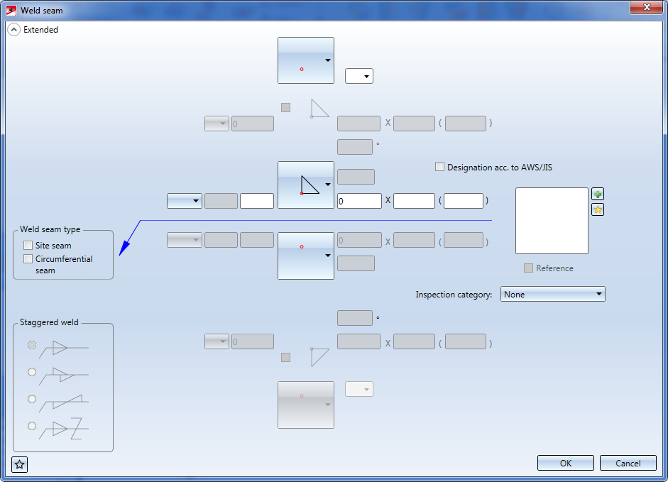
At the top of the dialogue window you can specify the settings for the weld seam tag, i.e. the weld seam type, and further data required for this type (e.g. seam thickness). Instead of a selection from dimension a to dimension z you can also choose an empty entry from the listbox.
Click the Settings  icon to open a dialogue window with extended setting options. It is largely operated in the same way as the dialogue window for the Insert weld symbol function, although the range of available function is smaller here.
Click OK to accept the current settings for the weld seam tag. The Weld seam dialogue will then be re-opened.
After specifying all required settings, you have the following options:
|
Apply |
The weld seam will be created according to the specified parameters. After creation of the tag the Weld seam function will remain active, and the selection of parts to be welded will be requested repeatedly. |
|
OK |
Same as Apply, but with the difference that the dialogue window will be closed. |
|
Cancel |
Use this button to cancel the Insert weld seam function. Edges in the list and edges which have not been welded together yet will be discarded. |
To insert the weld seam tag, right-click the weld seam after its selection, select the Insert weld symbol function in the context menu, and specify the start point of the tag by identifying a point or an edge.
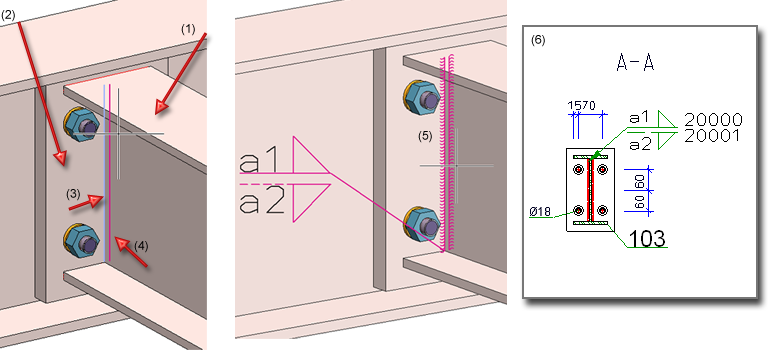
In the example shown below, a fillet weld has been inserted between the two cuboids (1) and (2). The powder marking lines (3) were determined automatically. Case A shows a symbolic, (4 = Length of lines), case B a solid representation.
Each weld seam main part has a corresponding feature log. It consists of a "superordinate" creation feature and, for each weld seam creation, one environment management feature for the actual seams. Please note that for weld seams which were created in one step, only one feature of this type will be created.
In the example shown below, the two weld seams on the left hand side were created in one step. In the process, the main part Weld seam (a) was created. After this, the weld seam function was called again (while the main part was still active) and the right weld seam was created. The feature log then contains the creation feature (b) and two weld seam features (c). In our example, feature (3) belongs to the two first created weld seams (for this reason there are four entries under Welding line list).
Please note:
 > ....
To ensure that the weld seams actually appear in the BOM, you need to assign the attribute "BOM-relevant" to the corresponding weld seam part.


Weld Seams (3-D) • Process Weld Seam (3-D) • Insert Weld Symbol (3-D) •Standard Parts (3-D)
|
© Copyright 1994-2019, ISD Software und Systeme GmbH |