Project: HiCAD 3-D

Dialogue Window for Detail Views

You define the settings for detail views in the New detail view dialogue window, which is automatically displayed when you call the Detail view function.

The settings in detail are as follows:


Sketch for the detail area

The area of a detail view is based on a 3-D sketch.

Activate this icon to create a new sketch.
HiCAD acivates the Sketch tab. Define the sketch plane and draw the sketch.

Activate this icon if you want to use sketches available in the drawing. Then identify the relevant sketch.

The sketch used is preserved even after the detail view has been created.

The sketch used is deleted after the sectional view has been created.


If a sketch that has been parameterised with HCM constraints contains variables, these will automatically be defined as variables of the view. When using the sketch in a detail view, a sectional view or a cut-out. If you then change the value of the view variables, all views of the current drawing will be updated and the corresponding detail views, sectional views and cuts-outs will be adjusted accordingly. The original sketch, however, remains unchanged. This means that you can adjust view fast and easily without having to change the corresponding sketch.


Please also read the notes on the purposes and representation of sketches. Sketches with the purpose Part will be cut in detail views, sketches with the purpose Create/Edit will not be cut.


Identification of detail views

Option

Effect

The selected detail area is identified in the original view (source view). The identification can take the form of an area contour, a circle or an ellipse. Select the identifier for the detail view in the list boxes of the Ident area. You can also choose a 2-letter code here, e.g. AC.

Click the symbol to specify the representation of the identifier. The following dialogue window will be displayed:
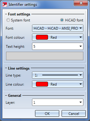
When this function is selected for the first time in the current drawing the default settings in the window are those specified in the Configuration Editor. To change these settings, open the Configuration Editor and select Drawing > Views > Ident > Details. When you call the function again, the last used text and line parameters will apply.

A caption is generated for the detail view. Define the entries that you want to be copied to the caption by activating the relevant checkboxes. If, for example, the detail view is not derived in alignment direction, activate the arrow and, if required, the angle.

If you want to define an individual caption for the view, click the icon.

The View caption window will be displayed. The available functions and parameters are the same as in the 3-D Text Editor. Specify the caption as required and exit the window with OK.

The caption is automatically centred above the view. You can, however, move the caption.

For captions in sectional views the template file VIEWHEADER_S.FTD in the HiCAD sys directory is available. Use this file to individually configure the captions in sectional views. When you create a new sectional view, the caption will be composed of the settings selected in the template file, the view designation and the caption components Scale, Arrow and Angle chosen in the dialogue window for sectional views.

By default, the FTD file is initially empty.


Hatching

You can also display section surfaces of a detail view in hatched format. To obtain a hatched display of the section surfaces, proceed as follows:

  1. Activate the With hatching checkbox . The current hatching setting is displayed.
  2. If desired, click the icon to choose another hatch pattern.
  3. Define the hatching line spacing and angle.


The hatching of the cut plane is influenced by the settings chosen in the Configuration Editor, at Drawing > Views - Cut surface hatching.

Special Views (3-D)Sectional and Detail Views (3-D)Views (3-D)

© Copyright 1994-2019, ISD Software und Systeme GmbH
Version 2402 - HiCAD 3-D
Date: 06/10/2019

> Feedback on this topic