|
|
Please note:
|
Usage assignments can now not only be defined for already existing assemblies and part types, but also for freely defined part types.
This allows you to apply your own configuration for drawing derivation to Steel Engineering series beams that have been created from 2-D cross-sections.
For example, you could define a part type called Series, and a usage assignment called Default(Series).
When you then create workshop drawings for model drawings with series beams and choose the drawing parameters From configuration, the configuration Default(Series) will be used for all series beams with the part type Series.
An example can be found here.
As of HiCAD 2018 SP1, dimensions of elongated plates that have been placed along a 3-D composite edge are calculated with the help of an (internally) developed plate (blank). This also means that, for instance, the width shown in the part attributes mask, is not necessarily identical to the width shown in the model drawing. As of SP2, this also applies to folded elongated plates.
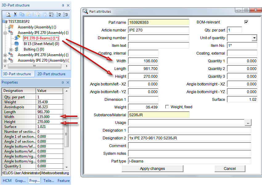
The widths and heights of profiles can now also be managed in the part attribute masks.
Please also read the information on the new and changed dimensioning rules for plates and railing segments in the News of the HiCAD Basics Help.
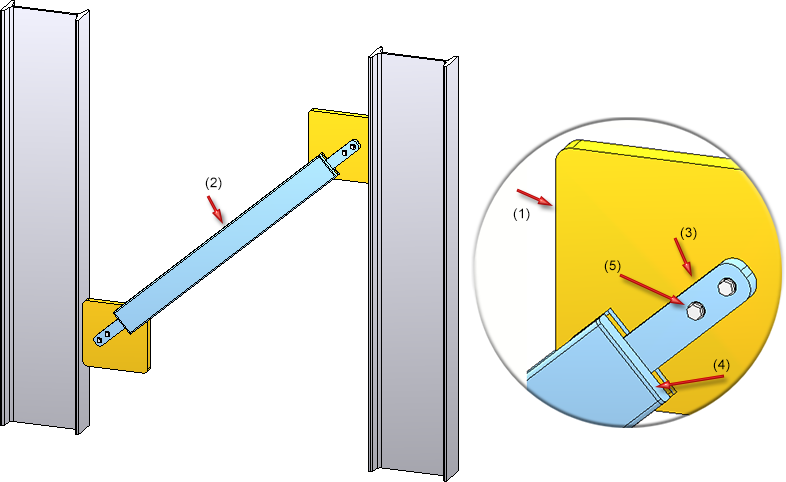
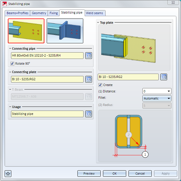
The Design Variant Stabilizing pipe connection has been redesigned.
The created connection consists of
When using the functions Exchange sketch or Process sketch in the Feature log of a glass that has been created with the Glass from sketch  function, the parameters for chamfers and offsets will now be taken over.
Excluded are offsets that were assigned to the individual line elements of the sketch with the Individual option. In this case, all offsets will be set to 0.
The DAST guidelines for weld seams have been implemented for the following Design Variants:
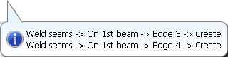
If the weld seam settings are changed in such a way that they are no longer in accordance with the DAST guidelines, the DAST designation will be marked with a  symbol. When you move the cursor over the symbol, a message will be displayed, e.g.:
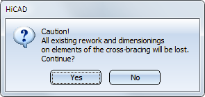
If you rework a cross-bracing subsequently (double-click on Feature) and then choose a different number of beams, reworks and dimensionings that may exist on elements of the cross-bracing may be lost. In such cases HiCAD will display the following warning message:
The Glass from sketch function has been revised. You have now the option to build glass panes with as many layers as you like.
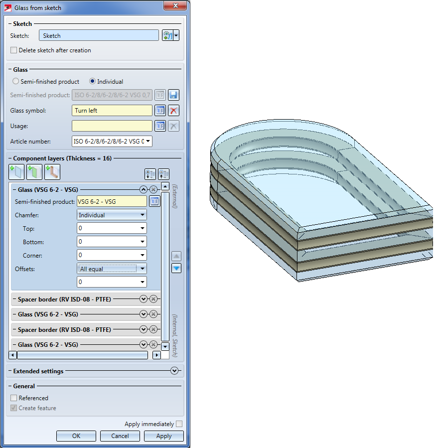
Glass panes can either be individually configured or used in the form of semi-finished products from the catalogue. An individual configuration can be directly taken from the dialogue window as a new semi-finished product stored in the catalogue.
The previous function Glass from sketch is currently still available as the "Glass from sketch (old)" function.
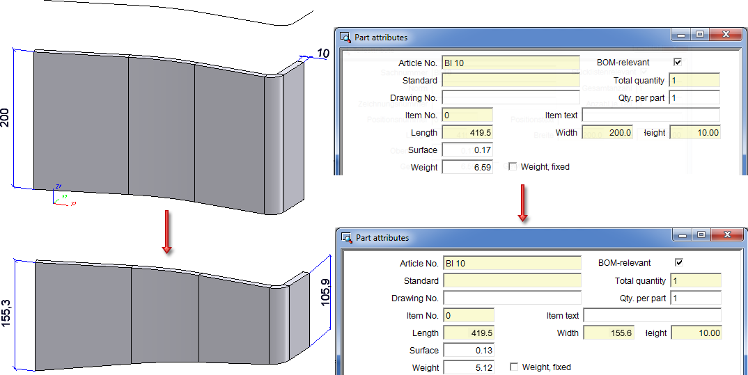
For elongated plates that have been inserted along a 3-D composite edge, the dimensions are now determined by means of the (internally) developed part (blank). This also means that, for example, the width shown in the Part attributes mask needs not necessarily be identical with the width of the part in the model drawing. The image below shows such a case: An elongated plate with a width of 200 was initially placed along a C-edge. A subtraction via translation was then applied to the part, which changed the width of the part.
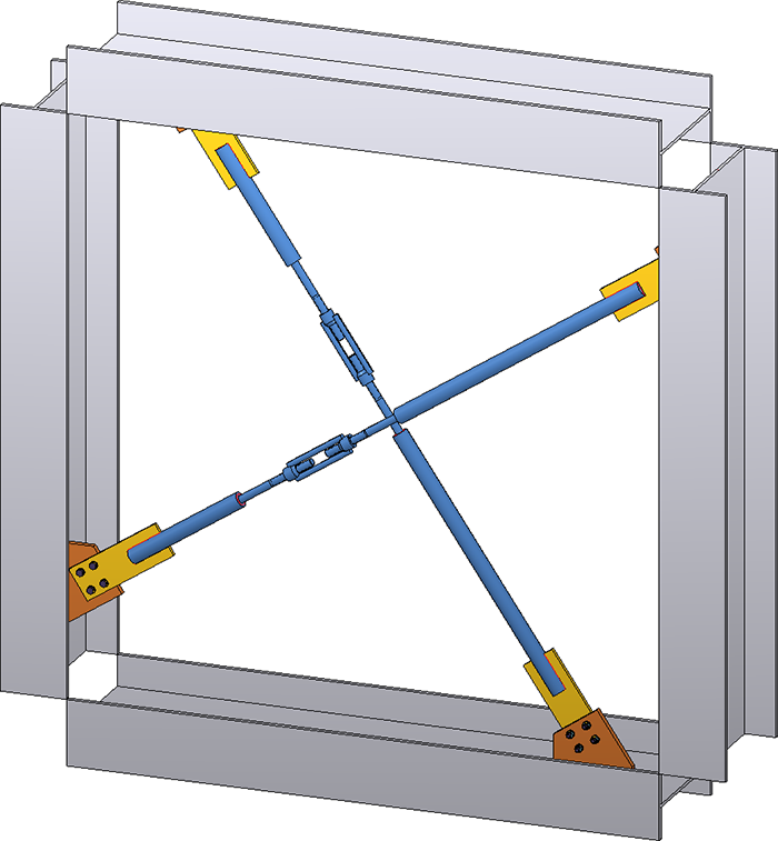
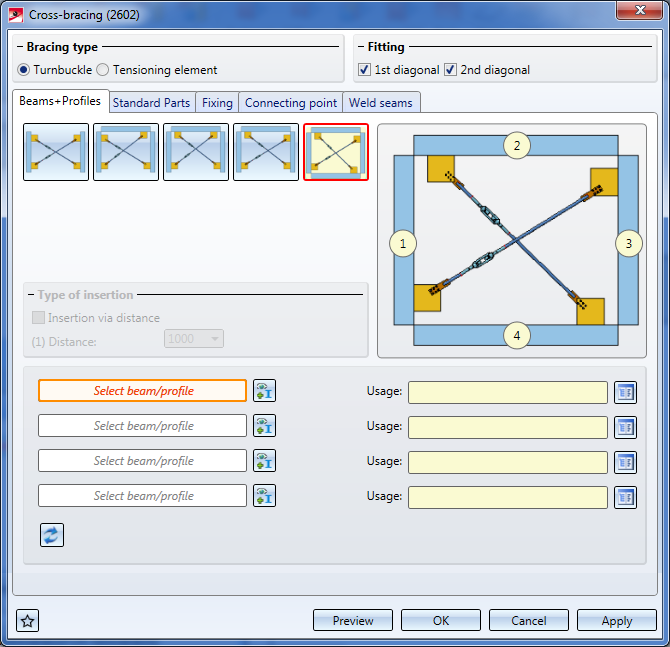
The new Cross-bracing (2602) design variant connects two, three or four beams by means of a cross-bracing. The cross-bracing can be created with a turnbuckle or a tensioning element, and with one or two diagonals.
In those Design Variants that offer the option to insert galvanization holes, the minimum distance to the flange or web required in the dialogue is now always the distance between bore edge and flange (or web). In some of these variants this distance used to be interpreted as distance between the centre of the bore and the flange (or web).
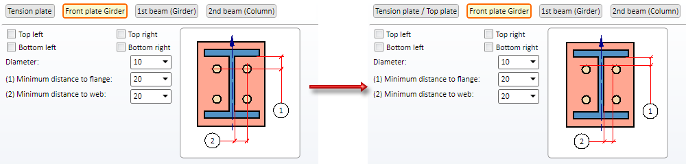
Left: Before HiCAD 2018 SP1; Right: As of HiCAD 2018 SP1
This change concerns the following variants:
Please note:
When you load a model drawing containing one of the above Design Variants created with a HiCAD Version before 2018 SP1, nothing will change. But when you process such a Design Variant, the distances to centres of bores will be shown in the dialogue, and will also still be interpreted as such- even if the dialogue window shows a different distance!
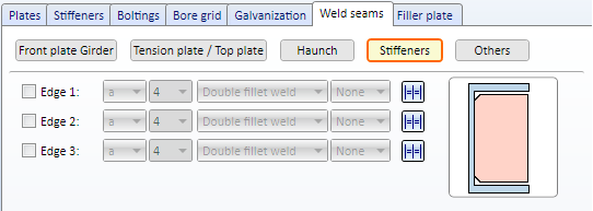
The dialogue windows for the Column connection, Frame corner (2203) and (2204) offer an additional tab for the settings of weld seams on stiffeners:
The following default settings of parameter configurations for Steel and Metal Engineering have been changed in the Configuration Editor at Automatic drawing derivation > Production drawing:
|
Parameter |
Old |
New |
|---|---|---|
|
Usage-dependent > name* > View group > Insert BOM |
In view group |
In drawing frame |
|
Usage-dependent > name* > View group > BOM: Position in view group |
Bottom left |
Bottom right |
|
Usage-dependent > name* > View group > BOM: Position in drawing frame |
Bottom left |
Bottom right |
*name is the name of the usage, or part, respectively, e.g. ASSEMBLY_BEAM or DEFAULT(I_PROFILE).
Furthermore, the BENENNUNG (Designation) attribute for quantity lists has been removed in the BOM configuration file Hicad_Stahlbau.RMS.
For Railings the following three new usage types are available in the Factory standards catalogue at Usage > Civil Engineering > Steel Engineering > Railing:
You can assign usage-dependent configurations for drawing derivations to these new railing elements.
The following configurations have been preset for the new usage types in the Configuration Editor at Automatic drawing derivation > Production drawing > Usage assignment:
|
Usage |
CONFIGKEY |
Utilized |
Consider for |
|---|---|---|---|
|
Post profile |
POSTPROFILE |
DEFAULT (STAHLROHRE) |
Yes |
|
Handrail profile |
RAILINGPROFILE |
DEFAULT (HOHLPROFILE) |
Yes |
|
Skirting board profile |
SKIRTINGPROFILE |
DEFAULT (FLACHSTAHL) |
Yes |
Furthermore, the default setting for the vertical rods used for infills has been changed:
|
Usage |
CONFIGKEY |
Utilized |
Consider for |
|---|---|---|---|
|
Rod |
WEBMEMBER |
DEFAULT |
Yes |
The default setting for Steel Engineering elements of the part type Round steel has also been changed:
|
Usage |
Part type |
Utilized |
Consider for |
|---|---|---|---|
|
All |
Round steel |
DEFAULT (STAHHLROHRE) |
Yes |
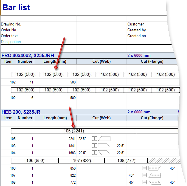
The long texts and short texts in the "images" of bar lists are now configurable. The ISD default setting is as follows:
The short text will be used if there is not enough space for the long text in an image.
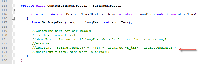
As of SP1 these texts can be also be configured individually if desired. The configuration takes place via the script HiCAD_Stahlbau.2201.0.cs (in the HiCAD sys directory) in Line 149/150, in the form as shown in the script:
|
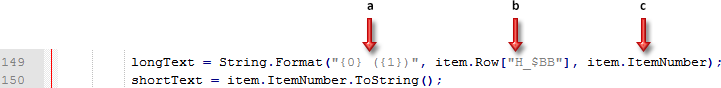
a |
Here the number of the attributes to be used for the long text is specified, and the text to be output in brackets is determined. Here: 2 attributes; the 2nd text appears in brackets |
|
b |
1st attribute; here: Article number ($BB) |
|
c |
2nd attribute; here: Item number (output in brackets) |
More examples:
|
Entry in CS file |
Meaning |
Example |
|---|---|---|
|
longText = item.ItemNumber.ToString(); shortText = item.ItemNumber.ToString(); |
Long text = Item number |
107 |
|
Short text = Item number |
107 |
|
|
longText = String.Format("{0} ({1})", item.Row["H_$BB"], item.ItemNumber); shortText = item.ItemNumber.ToString(); |
Long text = Article number (Attribute $BB) and Item number in brackets |
HEB 200 (107) |
|
Short text = Item number |
107 |
|
|
longText = String.Format("{0} ({1}) ({2})", item.Row["H_$BB"], item.Row["H_$05"], item.ItemNumber); shortText = item.ItemNumber.ToString(); |
Long text = Article number (Attribute $BB) and Part type ($05) in brackets and Item number in brackets |
HEB 200 (I - Profile) (107) |
|
Short text = Item number |
107 |
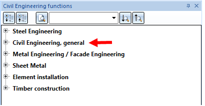
From Version 2018 onwards, the HiCAD Steel Engineering module will contain the connections that you can find in the Civil Engineering functions docking window at Civil Engineering, general.
With this variant two I-beams are connected with a bolted or welded beam frame corner. You can create the frame corner with or without stiffeners, haunched plates or other components, e.g. haunched flanges, web reinforcements and reinforcement plates or filler plates. It is also possible to insert stiffeners at the tension plate and ribs at the front plate, and also weld seams as well as to apply galvanization holes.
In contrast to Frame Corner (2203), the connection is made with a square haunch and the tension plate can also be conical here.
The connection to the girder can be either made with or without front plates.
Requirements for the installation of a frame corner are:
Example of a frame corner with an added tension plate
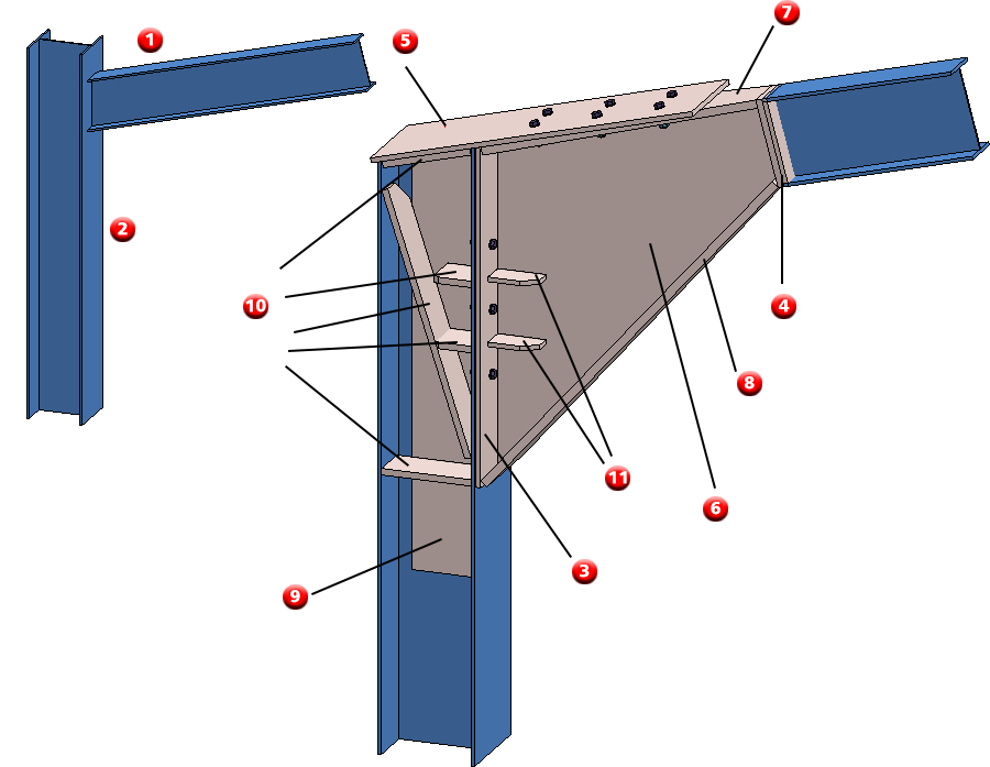
(1) girder, (2) column, (3) front plate at column, (4) two front plates at girder, (5) tension palte, (6) haunch, (7) haunched flange top, (8) haunched flange bottom, (9) web reinforcement, (10) stiffeners, (11) ribs
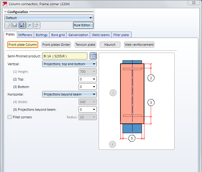
The Column connection, frame corner (2204) dialogue window will be displayed.
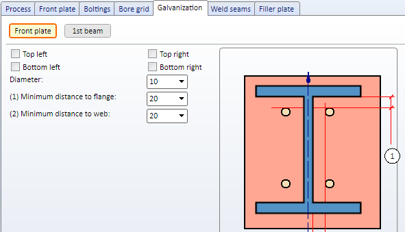
The Design Variants Front plate connection to Web/Flange Side (2320) and Beam to Web with 2 Plates and Stiffener (1211) allow to apply galvanisation holes in beams. For this, the tab Galvanisation has been enhanced accordingly within the dialogue boxes.
Settings for the 1st beam
Here, you can choose via the checkbox Edit if either holes or web cuts should be integrated.
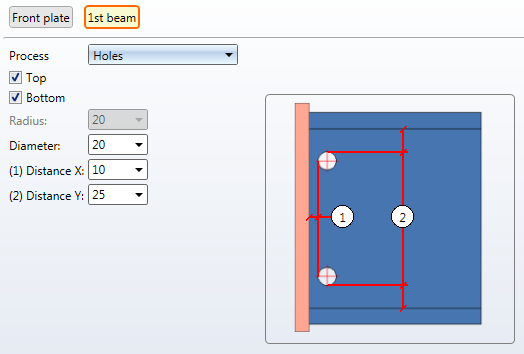
For integrating the web cuts, you determine the radius and the fitting position (top and/or bottom). For installing the holes, you determine the installation position (top and/or bottom), the bore as well as the distance to the plate (1) and beam edge (2).
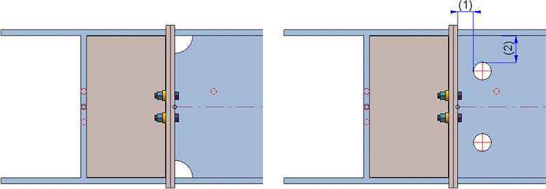
On the left: web cuts, on the right: holes
As far as the insertion of series beams is concerned, it has not been possible so far to insert an additional divergent beam via the function dialogue option Beam.
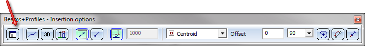
This problem is fixed in HiCAD 2018 and upwards, i.e., you can use this option to choose another standard part type before defining the next fitting point.
So far, it has not been possible to manage the display type of beams (exactly or simplified) via parameter configuration options for steel engineering. From HiCAD 2018 and higher this is not the case anymore.
The default settings have to be defined via the configuration editor under Steel engineering > Representation. The default settings are Simplified.
Dimensioning and annotations for beams, plates and sheets in workshop drawings can (if desired) be placed only on the visible outer side, i.e. bores/processings that are displayed with dashed lines in the HiddenLine dashed representation will not be dimensioned in the corresponding view.
To suppress the dimensioning for hidden bores/processings, the following requirements must be met:
</PARAM><PARAM Name="IGNOREHIDDENSUBPARTANDBORES" Typ="INT" Value="1">
The settings for the dimensioning only apply to dimensionings via dimensioning rules.
To suppress the annotations for hidden bores/processings, the following requirements must be met:
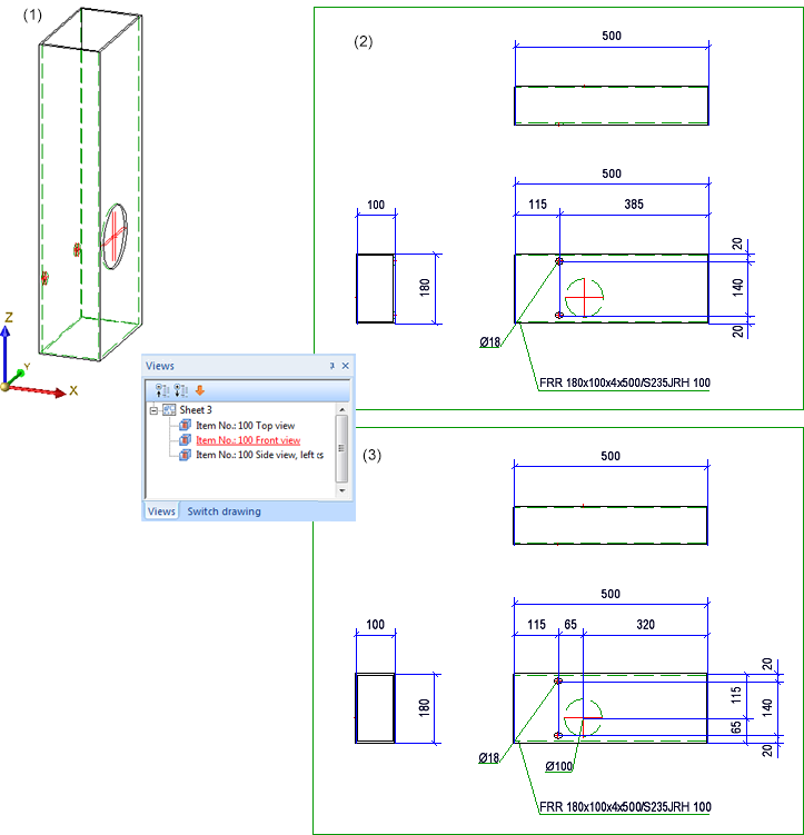
(1) Original beam; (2) Workshop drawing with suppressed dimensioning + annotation of hidden bores; (3) Without dimensioning + annotation of hidden bores
When calculating the weights of bulb plates, the values in the columns GEW (Weight) and HGEW (Avoirdupois weight) of the catalogue will now be evaluated.
In the Configuration Editor at Automatic drawing derivation > Production drawing > Avoid multiple sectional views you determine that sectional views with the same content will only be created once in the workshop drawing. Sectional views are considered equal if
Sectional views for plates outside of the plate end (front plates, top plates, base plates mean the same) are generally unequal.
If you have chosen the Steel/Metal Engineering template in the HiCAD Parameter configuration dialogue window (double-click ParKonfigComp.exe in the exe directory of your HiCAD installation to open this window), the Avoid multiple sectional views checkbox will be active by default.
A prerequisite for the start of the Staircase or Railing Configurator is that the current drawing contains a main assembly. If this is not the case, the following message will now be displayed.
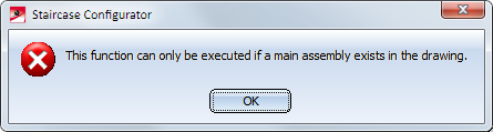
Click OK and create a new main assembly and call the function again.
No automatic creation of a main assembly will take place anymore, as was still the case in older versions up to HiCAD 2017.

|
© Copyright 1994-2018, ISD Software und Systeme GmbH |