Beam from Sketch (3-D SE)
Steel Engineering > New > Beam from sketch 
This function derives a beam from an arbitrary sketch existing in
the drawing
- Create the corresponding
sketch, if required. When drawing the sketch, note that the distance
of the sketch from the coordinate system is crucial for the subsequent
position of the fitted beam. The beam is fitted at the same distance from
the XY-plane as that between the sketch and the origin of the coordinate
system. The beam axis is always placed in the coordinate origin.
- Specify a 3-D point for the position of the beam axis.
- The dialogue window for sketch beams will be displayed. Enter the article number for the beam. SKETCH BEAM is proposed as
the default setting.
- To assign further data (weight, avoirdupois weight, surface etc.) to the beam, activate the corresponding checkbox. and enter the desired value.
- Select the material.
- If you want the sketch to be deleted after creation of the sketch, activate the corresponding checkbox.
- Close the window with OK.
The fitting dialogue window will then be displayed. It is similar to that for the fitting of standard beams. Choose the desired
insertion options, specify
the start point and, if applicable, the end point of the beam.
From a sketch (left) derived beam, (1)
Point for beam axis
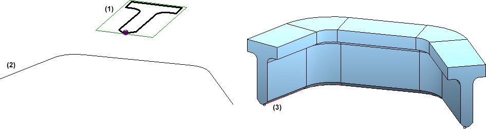
The beam (3) was derived from a sketch (1) and inserted along a c-edge (2)
 Please note:
- You can subsequently change the cross-section of a beam
derived from a sketch using Feature
technology. The sketch is entered into the feature log and can be
loaded and processed there.
- The moving of points in a defined rectangle crosswise to the beam axis is also possible for beams derived from sketches (this option is not possible for other beams).
- You can also use the Beam from sketch (3-D SE) function in the context menu of the sketch for the creation of beams. Please note that if the sketch belongs to an assembly, the beam will also be assigned to this assembly.


Fitting
Options for Beams (3-D SE) • Insert Beams
(3-D SE) • Steel Engineering Functions
|
© Copyright 1994-2018, ISD Software und Systeme GmbH
Version 2302 - HiCAD Steel Engineering
Date: 28/09/2018
|
> Feedback on this topic
|