P+ID > Connections > C.Type![]()
P+ID > C.Type  > Connection, diagonal
 ![]()
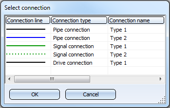
There are three different types of connections, i.e. connections that can be created between the connecting points of symbols: Pipe connections, Signal connections and Drive connections.
Clicking opens a pull-down menu with the Connection, diagonal function.
For both functions, a list of defined connection types will be displayed. Select the desired connection type with a double-click:
If the Activate sketch mode checkbox has been activated in the Settings > Connections tab, you can sketch connections.
When you identify a start or end point, a snap-area in the vicinity of the respective cross-hairs position will be recognised. HiCAD will identify the connecting point that is nearest to the cross-hairs position. If desired, the snap option can be deactivated via the context menu for further point specifications on the connection line. You can also specify the size of the snap area in the Connections tab of the P+ID Settings (Settings > Settings).
With a value of 3 and the default grid increment of 2.5 mm, connections are recognised in the area surrounding the cross-hairs represented below.
A = (3 + 3) * 2.5 mm = 15 mm
If the Only horizontal and vertical option is active, the connection line of the previous point is correspondingly adjusted.
Line parameter values can be pre-set for each category of connection with the Settings function. If Only horizontal or vertical is set for Direction of connection, oblique line sections are automatically horizontally or vertically aligned.
For each symbol connection, you can specify the category of connection permitted via the entry for the dialogue type, Connection in its data mask. Normally, the default entry in the symbol data mask from the symbol library comes with the symbol. You can, however invoke the Edit symbol function. The dialogue text for a connection is made up of an identification character for the valid connection category followed by the connection designation as it should appear in the drawing. This is normally a connection number.
|
ID |
Meaning |
|---|---|
|
X |
All connections are permitted |
|
R |
Only pipe connections permitted |
|
A |
Only drive connections permitted |
|
S |
Only signal connections are permitted |
Example: "R2“ indicates that only a pipe connection is valid for the associated joint, and that the connection will be indicated by "2" in the drawing. If a connection line is drawn from a symbol for which a flow direction has been specified, HiCAD will indicate whether the selected flow direction is permissible for this connection.
After creating a connection line, you can directly create another one with the same connection type without having to open the selection list once again.


|
© Copyright 1994-2018, ISD Software und Systeme GmbH |