
P+ID > Settings > Settings >Connections
You can preset line parameters for
As there are two different types of representation available for pipe and signal connections, HiCAD differentiates between line parameter allocations. You can switch between these representations when creating connections.
Layer No. 1 should be set for pipe and drive connection, while Layer No. 3 should be set for signal connections. Please refer to the Visualisation chapter for more information about layers.
The tab consists of the following areas:
In the Connections area you can define an arbitrary number of connection types. Each connection will obtain a name. The name need however be unambiguous within the connection types (Pipe connection, Signal connection, Drive connection). The two connection types for pipe connections in older HiCAD versions have the names Type 1 and Type 2. The two old connection types for signal connections, too, have the names Type 1 and Type 2. The old connection type for drive connections has the name Type 1 here.
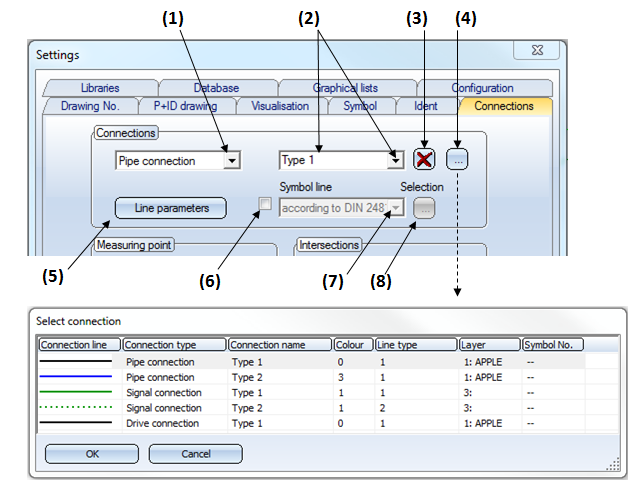
Show existing connection types (4)
The connection types are listed in a dialogue window. The row that corresponds to the selection made in the fields (1) and (2) will be highlighted. A double-click on the row closes the window, and automatically sets (1) and (2) to the selected connection type. Instead of double-clicking the desired row, you can also mark the row with a single-click and confirm the selection with OK.
Change a connection type
Select, via (4) or (1), the connection type that you want to change. Specify the desired settings for this type via (5), or via (6), (7) and (8).
Define a new connection type
In the field (2), enter the name of the new connection type. As soon as you click on another button, the question New connection type? (No = Rename), or the message Creating new connection type will be displayed. Answer with Yes or OK to create the new connection type. If you select Cancel, the new name will be removed from the field (2) again. Specify the properties for the new connection type via (5), (6), (7) and (8).
Delete a connection type
Select, via (4), or (1) and (2), the connection type that you want to delete. Then click (3) to delete it.
Rename a connection type
Enter the name of the new connection type in the field (2). As soon as you click on another button, the question New connection type? (No = Rename). Answer with No to accept the new name. If the message Creating new connection type is displayed, the selected connection type was a default connection type. If you select Cancel, the new name will be removed from the field (2) again.
Create your own symbol lines for pipe connections:
On the Connections tab you can specify types using symbol lines (8) for pipe connections.
Supplied with HiCAD are symbol lines according to DIN 2448. The contents of this selection list are specified in the makro2d\symblinien2481_list.dat file:
# Belegung der Liste zur Wahl einer Symbollinie
# Stufe (hier nur 1)|Icon-Dateiname (ohne Ext.)|Text oder $nnnn und Kommentar|Rückgabewert
# Der Rückgabewert ist hier der Name des Symbols in \hicad\sys\Symtab.sza.
# Die Textnummer $nnnn bezieht sich auf die TEXTMAP*.MAP Dateien in "\hicad\HICAD TextFiles".
# Die Text-ID wird wie folgt gebildet: TEXTE1AN<nnnn - 1>
# Beispiel: nnnn = 0231 --> Text-ID = TEXTE1AN230
image
ICONSIZE 80 16
T0|$0248 Stoffdarstellung nach DIN 2481
T1|$0249 Linienart / Stoff
1|sy2481_0001|$0231 Dampf|3501
1|sy2481_0002|$0232 Ölhaltiger Dampf|3502
1|sy2481_0003|$0233 Kreislaufwasser|3503
1|sy2481_0004|$0234 Ölhaltiges Wasser|3504
1|sy2481_0005|$0235 Rohwasser|3505
1|sy2481_0006|$0236 Schlammwasser, Schmutzwasser|3506
1|sy2481_0007|$0237 Lösungen, Chemikalien|3507
1|sy2481_0008|$0238 Öl|3508
1|sy2481_0009|$0239 Flüssigmetall|3509
1|sy2481_0010|$0240 Luft|3511
1|sy2481_0011|$0241 Brennbare Gase|3512
1|sy2481_0012|$0242 Nicht brennbare Gase|3513
1|sy2481_0013|$0243 Feste Brennstoffe|3514
1|sy2481_0014|$0244 Brennbare Abfälle|3515
1|sy2481_0015|$0245 Sonstige Stoffe|3516
1|sy2481_0016|$0246 Weitere Kennzeichnung 1|3517
1|sy2481_0017|$0247 Weitere Kennzeichnung 2|3518
The meaning of the entries is explained in the first lines.
You can create further files with selection lists, which can then refer to symbol lines defined by the user.
Let us assume that you want to create a new selection list with initially only one entry referring to a new symbol line.
The following steps will be required:
# Belegung der Liste zur Wahl einer Symbollinie
# Stufe (hier nur 1)|Icon-Dateiname (ohne Ext.)|Text oder $nnnn und Kommentar|Rückgabewert
# Der Rückgabewert ist hier der Name des Symbols in \hicad\sys\Symtab.sza.
# Die Textnummer $nnnn bezieht sich auf die TEXTMAP*.MAP Dateien in "\hicad\HICAD TextFiles".
# Die Text-ID wird wie folgt gebildet: TEXTE1AN<nnnn - 1>
# Beispiel: nnnn = 0231 --> Text-ID = TEXTE1AN230
image
ICONSIZE 80 16
T0|$0248 Stoffdarstellung nach DIN 2481
T1|$0249 Linienart / Stoff
1|sy2481_0001|$0231 Dampf|3501
# Belegung der Liste zur Wahl einer Symbollinie
# Stufe (hier nur 1)|Icon-Dateiname (ohne Ext.)|Text oder $nnnn und Kommentar|Rückgabewert
# Der Rückgabewert ist hier der Name des Symbols in \hicad\sys\Symtab.sza.
# Die Textnummer $nnnn bezieht sich auf die TEXTMAP*.MAP Dateien in "\hicad\HICAD TextFiles".
# Die Text-ID wird wie folgt gebildet: TEXTE1AN<nnnn - 1>
# Beispiel: nnnn = 0231 --> Text-ID = TEXTE1AN230
image
ICONSIZE 80 16
T0|Own symbol lines
T1|Line type / Meaning
1|Sy3522|Salt water|3522
The assignment between an icon and a symbol name must be unambiguous.
# Menü-Definitionen zu Symbollininezusammenstellungen
# max. 10 Dateien
# Dateiname (ohne Ext.)|Text
# oder
# Dateiname (ohne Ext.)|$<nnnn> Text
# (die Textnummer <nnnn> bezieht sich auf TEXTE1AN<nnnn - 1> in der Textmap-Datei)
#
symblinien2481_list|$756 DIN 2481
own_symbolline_list|Own
You can now choose between 2 selection lists:
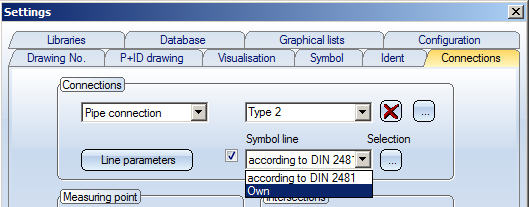
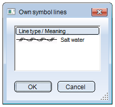
If you select "Own", the following dialogue appears:
Restore default values
Clicking on Default values:
Clicking on Cancel:
A gauge symbol is usually linked to other symbols in a flow-chart by a signal, thus creating a link between the connecting points of symbols. It is, however, often necessary to represent the location of a measuring point independent of symbol connections, e.g. in a vessel symbol or on a pipe joint. A measuring point can be located in an optional position and is the start point of a signal connection.
Diameter and line parameter can be set.
You can specify whether a link should run in all directions or only in a horizontal or vertical direction.
With the second setting, an oblique line automatically swings from horizontal to vertical during line creation. Independent of the setting selected here, a connection line can be extended in an optional direction from the first link section.
The Activate sketch mode option enables you to sketch links.
This option enables you to specify the type of connection that should be recognised by the Interrupt at intersections function.
If the Pipe connections in foreground option is is active, the signal link is interrupted at pipe connection crossings, irrespective of the direction of the connection.
When you draw a connection, a snap area about the cross-hairs is respected when you identify a start or end point. The connection point nearest the position of the cross-hairs can be identified within the snap area. The values specified with this option determine the size of the area.
In older versions, connections between different pipelines could only be created via a separation symbol. This restriction can now be removed if desired. In the Connections tab of the Settings dialogue, activate the Allow connections between different pipelines checkbox.
Example:
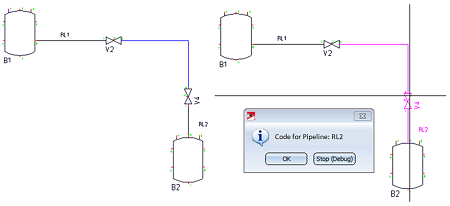
A pipe connection (highlighted blue) has been created from the right connection of valve V2 in pipeline RL1 to the upper connection of valve V4 in pipeline RL2. If you use the Show pipeline function to check the assignment of symbols and connections to pipelines, you will see that the new connection has been assigned to pipeline RL2.
Generally the following applies: The pipeline connection will be assigned to the pipeline to which the symbol on whose connection the pipeline connection end point is set belongs. “End point” here refers to the order of the point entries when drawing the pipeline connection.
If you do not want to assign the new connection to any of these pipelines, right-click, as soon as the cursor for start point entry is visible, and select New pipeline from the context menu. Then draw the connection, as usual. A new pipeline symbol will then be created, to which the new connection will automatically be assigned.

|
© Copyright 1994-2018, ISD Software und Systeme GmbH |