
Plant Engineering > Isometry / Pipe Spool Drawing > AutoGenerate isometry 
Plant Engineering > Isometry / Pipe Spool Drawing > Generate pipe spool drawing 
Isometry + pipe spool drawing > Create > AutoGenerate isometry 
On the right hand side of the Plant Engineering Isometry dialogue window, you can define various options and actions for the isometry documents to be created:
The settings apply to the pipeline which is marked on the left hand side of the list. If you want to apply the settings for one pipeline to all other selected pipelines, click the Apply to all pipelines button.
For the isometry or pipe spool drawing of pipelines you can use different drawing frames. Select the desired frame from the listbox. If you do not want to use a drawing frame, leave the corresponding input field empty.
When creating a Plant Engineering isometry you can preset the scale for the isometry if required. If you do not preset the scale, HiCAD determines the scale automatically. After creating an isometry, the last calculated scale is saved and can be adapted before re-creating the isometry. Once set, the scale remains the same until it is deactivated again (and a new isometry is created while the scale is deactivated).
 Please note:
You can specify via activation of the appropriate checkboxes which of the actions below you want to be executed on the pipelines.
Click the Select all button to activate all actions in one step.
If this option is active, the pipeline will be shown in a non-scale representation, in order to provide a well-structured view of the drawing. The straight pipes will be shortened (or lengthened) in such a way that all entries will have enough space. The settings specified on the Pipe shortening tab will be considered for the calculation of the length change.
 In older HiCAD versions, loops in pipelines were never considered for pipe shortenings. This behaviour has been changed with HiCAD 2014 SP2, i.e. loops can also be considered. If you prefer to use the old procedure, start the Configuration Editor, select Plant Engineering > Isometry and Pipe spool drawing, and deactivate the Apply pipe shortening to pipeline loops checkbox.
HiCAD creates a new sub-part of the pipelines main part, i.e. RBL0001, for dimensioning. The sub-parts SDR_ANL and MSL_ANL RBM_ANL are in turn created. The sub-parts Y_ANL_nnn containing rise triangles, are attached to the sub-part SDR_ANL. Rise triangles are consecutively numbered, i.e. nnn = 001, 002, 003 etc. Hi-CAD assigns any existing projection lines to MSL_ANL, e.g. automatically created projection lines for circular arcs.
Please note:
Guidelines are only insertion aids for layout plans and do not influence the dimensioning in isometric drawings; pipelines that begin or end with an elbow or contain a 180° bend are fully dimensioned in isometric drawings.
 You have the option to display an overview of welded connections in BOMs. For this to happen, go to Plant Engineering > Bills of Materials in the Configuration Editor and activate the checkbox of the parameter Supplement BOMs with an overview of welded connections.
 The image below shows a pipeline to which a vessel, a pump and another pipeline have been connected.
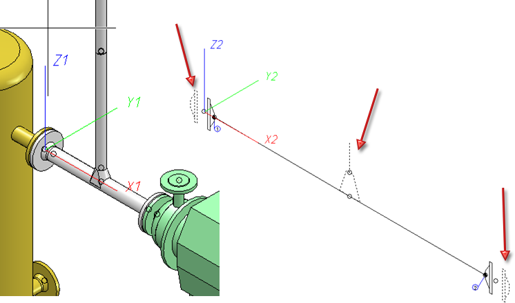
When indicated elements are used, another level called ~ConnectedElements will be added to the 3-D part structure of the pipeline isometry. Beneath this item you will find a sub-item called ~Component for each indicated component, and a sub-item with the name of the indicated pipeline.
Structure of the above example
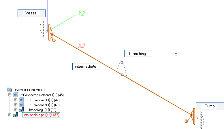
If you want to exclude any indicated parts from the representation, you have the option to remove them by rendering them invisible: Right-click the item in the ICN and choose the corresponding function beneath Visualisation.
You can only indicate such parts that also exist in the original drawing. This is important in cases where a pipeline isometry is the original drawing from which another isometry has been derived. One concrete use case would be an isometry that has been spread over several sheets. Here, it would not be possible to perform a subsequent indication of elements which do not exist in the original drawing. If you spread an isometry over several sheets using the Specify division option, the corresponding partial pipeline isometries will be added to the elements to be indicated and will then also appear in the 3-D part structure beneath ~ConnectedElements.
 In this context, please also read the notes on the Representation of Multi-Pipe Clamps.
A Projection can be chosen for each individual pipeline. When you do so, the chosen projection of the pipeline will be shown in the HiCAD drawing area.
To assign a projection to a pipeline, proceed as follows:
 With regard to the selected projection please note the following:
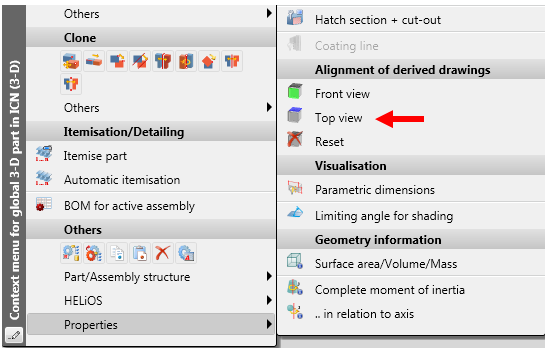
The functions beneath Alignment of derived drawings in the context menu of assemblies allow you to determine whether the active view is to be interpreted as  Front view or
 Top view of derived drawings. This means that a View CS will be defined for the front view or top view of the corresponding assembly.
These functions can also be applied to pipelines. In the ICN, right-click on the pipeline, open the Properties sub-menu and choose the desired function.
Isometry and pipe spool drawing will then consider the view coordinate system that was defined in this way:
 function that determines in which coordinate system the coordinates in dimension tags are to be calculated remains unaffected by this.
 To Reset the selected alignment, choose the same -named function in the context menu of the pipeline.
The alignment chosen for a pipeline can be marked accordingly in the model drawing.
Example:
The image below shows a pipeline for which no view alignment has been set. For the isometry, the Isometric projection 1 has been chosen.
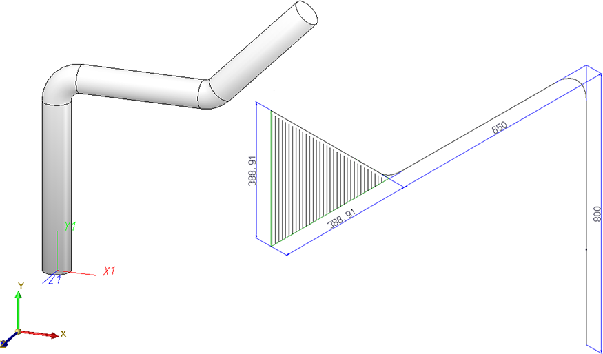
If you now open the context menu with a right-click, choose Properties > Alignment of derived drawings > Front view , and select the marked surface (1) in the image below, this will affect the isometry:
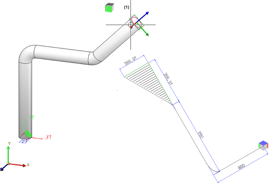
In the next image, Properties > Alignment of derived drawings > Top view  has been chosen, and then the marked surface (1):
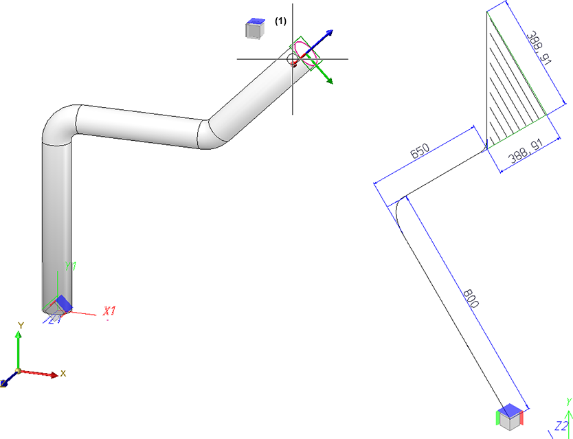
Create new drawing
If this checkbox is active (default) a separate drawing file will be created for the pipe spool drawing. If the checkbox is inactive, the pipe spool drawing will be generated in a new sheet area of the current drawing. You can preset in the Configuration Editor whether the checkbox should be active or inactive by default: Select Plant Engineering > Isometry and Pipe spool drawing, and activate or deactivate the Always generate pipe spool drawing in new drawing file checkbox.
View configuration to be used / View prioritization
In the Configuration Editor (ISDConfigEditor.exe) you can define view configurations for pipe spool drawings. These can then be selected from a list box. The views belonging to a configuration can be selected from a listbox. The views belonging to the selected configuration are listed beneath View prioritization. Each
You can specify the following parameters for a view:
The view configurations themselves have the following properties:
If there are several views you have the option to change their order using the  and
and  buttons next to the list. The uppermost view is the main view of the pipe spool drawing. The main view contains all pipe spool drawing elements, such as dimensioning and item number tags. If any item number tags in the main view belong to hidden parts, they will be passed on to the next view, taking the order of the other views into account.
The item number tags are distributed according to the following logic:
All item number tags the base points of which are hidden by a part, will be assigned to the next view. If some base points are still covered in this next view, they will be assigned to the subsequent view etc.
This procedure will be repeated until all item number tags could either be finally assigned to a view, or until all available views have been tried out. In the latter case, all remaining item number tags will then be assigned to the main view.
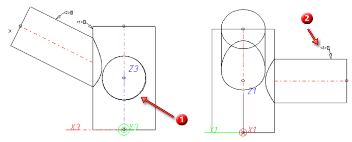
Example:
In the image below an inserted pipe points to the back and is therefore be hidden (1) if the construction is viewed from the front (1). Its item number tag has therefore been assigned to the second view (2):
Templates for own view configurations in pipe spool drawing
If you want to use your own view configuration, use the following, predefined templates in the Configuration Editor, and derive new view configurations from them. You can then configure these derived templates according to your requirements, e.g. you can add new views.
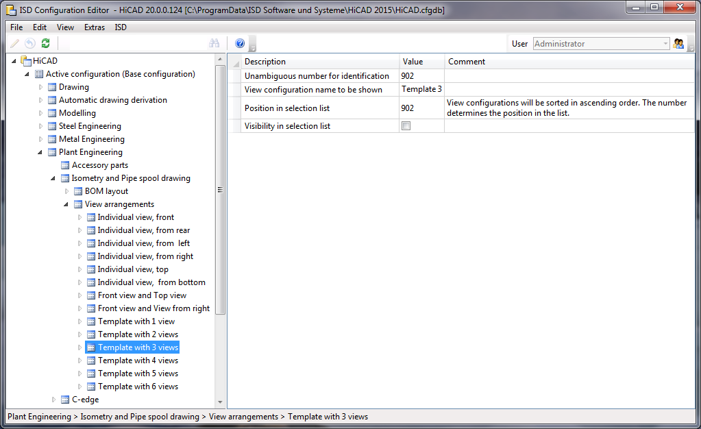
 Please note:

AutoGenerate Isometry (Iso)• Isometry and Pipe Spool Drawing (PE) • Isometry and Pipe Spool Drawing Functions for the Layout Plan (PE)
|
© Copyright 1994-2018, ISD Software und Systeme GmbH |