 Front view or the
 Right-click > Properties > Alignment of derived drawings ...
Use these functions in the context menu of 3-D parts to specify for assemblies, general 3-D parts, beams, Sheet Metal parts, Steel Engineering plates and pipelines whether the active view of a derived drawing is to be considered to be the
Front view or the
 Top view.
This setting influences the alignment of the assemblies, parts, beams, sheets and plates in derived drawings as well as the pipelines in isometries and pipe spool drawings.
If you want to undo the chosen alignment, Reset  .
.
The chosen alignment is marked accordingly in the drawing:
Left: Active view as front view; Right: Active view as top view
If the assembly or the view is rotated, the marking of the parts will be adjusted accordingly:
The visibility of the marking can be switched on or off via the settings in the Configuration Editor at System settings > Visualisation > Show alignment of active 3-D part in drawing:
 Important:
When applying the Active view as front view or the Active view as top view function to beams and plates, HiCAD will check whether the new alignment is actually allowed.
Please note the following:
The result of the check will then be shown in a dialogue window. Here it will be listed for which of the chosen plates the new alignment was successful, and to which no new alignment could be applied.
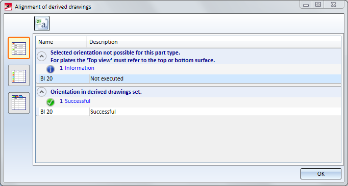
Use the symbols on the left to switch between the following representations of the list:
 Detailed list
 Abridged list
 List with several tabs
Click the  symbol to save the result list as a CSV file.


Part Properties (3-D) • Surface, Line ans Edge Parameters • Colour Editor • Model and Process Parts (3-D) • Derived Drawing - Active View as Front View/Top View
|
© Copyright 1994-2018, ISD Software und Systeme GmbH |