

The information about how two connections are joined to each other are saved in a non-visible, auxiliary connection part. This part contains the BOM data, i.e.:
The following functions are available:
|
|
|
|
|
|
|
|
These functions can also be applied to pipe spool drawings.
 Important:
The removal and re-creation of connection information is only possible in the layout plan, but not in the isometry or pipe spool drawing!
Isometry + Pipe spool drawing > Settings > Show/Change connection info 
Plant Engineering > Isometry / Pipe Spool Drawing > Ref.  > Show/change connection info
Use this function to interactively check or modify connection information at the individual connecting points. Such modifications are necessary if any connections do not comply with the general presettings.
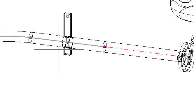
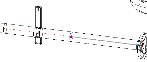
If you move the cursor over a connection, the connecting points will be highlighted in a different colour. If two or more parts converge in one connection, the relative position of the cursor will determine the connection info of which part will be displayed. In the example below the information of the left pipe part (upper image) and the information of the right pipe part (lower image) is selected:


The selected point will be displayed in the Marking colour 1, selectable points in the Marking colour 3, and the pipe part in simplified line representation with named point with reduced intensity.
In the shown example, the left pipe is a bent pipe with clamp. Here, two additional points are displayed. The graphic cursor is located between these points. As these points are no connecting points, they are displayed in reduced intensity, and the nearest possible connecting point will be selected.
Left-click to apply the selected point (Marking colour 1). The Connection dialogue box will be displayed.
Next to the Place of const. area it will be shown whether 1 or 2 connections are located at the identified point. If there are 2 connections it will be checked whether their data actually match.
Click Info to display the attributes of the assigned type. Click Select new to select a different type. If desired, you can also change the place of construction of the connection. Click OK to apply the changes, click Cancel to discard them. The cursor will then reappear, enabling you to process further connections. Right-click to end the function.
 Please note:
If there are several branching parts on one branching point, the connecting points of these parts coincide in the branching point. To show or change the connection info of such a connecting point, first select the point (with Point option J), and then select the part the connection info of which you want to change.
 You have the option to display an overview of welded connections in BOMs. For this to happen, go to Plant Engineering > Bills of Materials in the Configuration Editor and activate the checkbox of the parameter Supplement BOMs with an overview of welded connections.
Plant Engineering > Isometry / Pipe Spool Drawing > Ref.  > Create connection info
If no pipeline is active, use the graphic cursor to identify a part in the pipeline you want to process. When HiCAD asks for confirmation, respond with Yes.
No other actions are required. HiCAD creates the information for the active pipeline according to the predefined settings.
Plant Engineering > Isometry / Pipe Spool Drawing > Ref.  > Delete connection info
If no pipeline is active, use the graphic cursor to identify a part in the pipeline you want to process. When HiCAD asks for confirmation, respond with Yes.
No further actions are required. HiCAD deletes all connection information from the active pipeline.

Isometry and Pipe Spool Drawing (PE/Iso) • Isometry and Pipe Spool Drawing Functions for the Layout Plan • Plant Engineering Functions
|
© Copyright 1994-2018, ISD Software und Systeme GmbH |