
Plant Engineering > Guideline Tools > Create guideline
This example shows the effect of the Always project points on axes checkbox of the Guideline Editor.
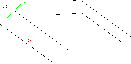
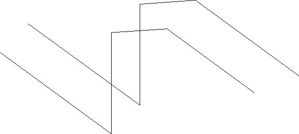
Let us assume that you want to create a new guideline running parallel to the guideline shown below.
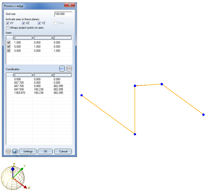
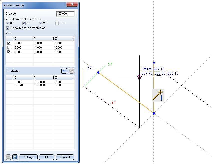
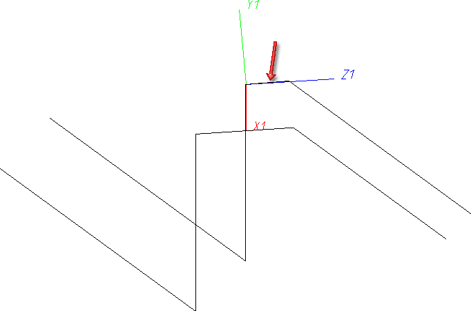
Choose the Create new guideline function. The Guideline Editor opens. Specify the first point.
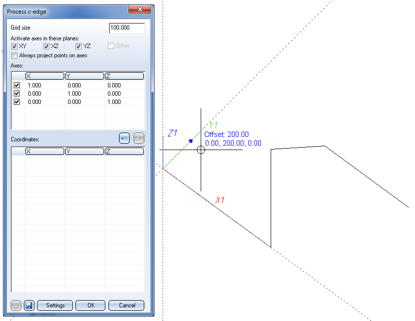
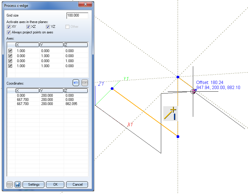
If you now attempt to pick the second point you will notice that it will not be projected onto the required axis.
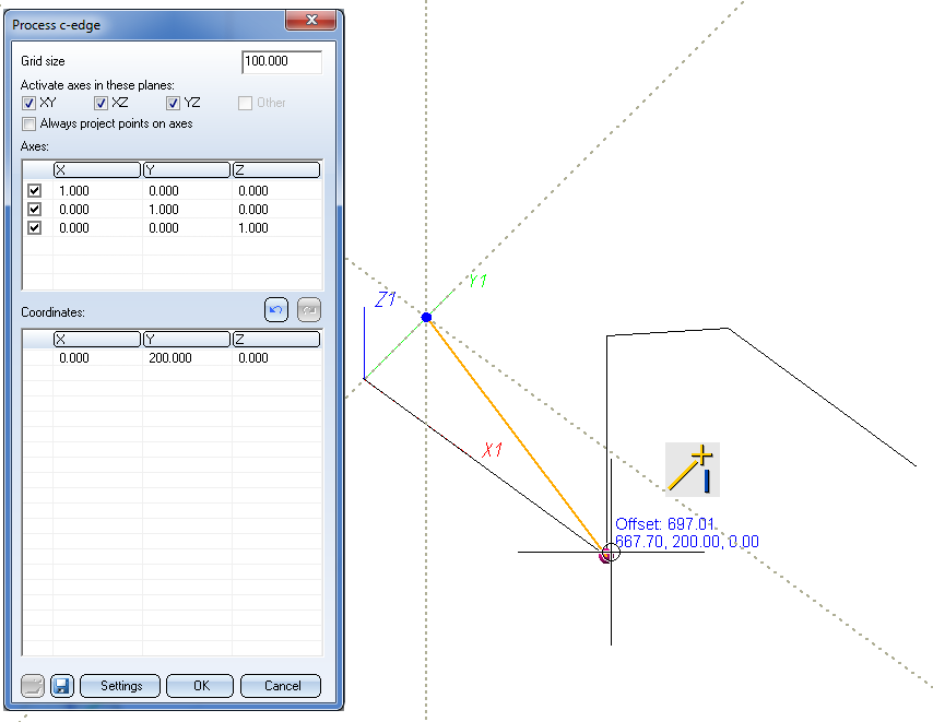
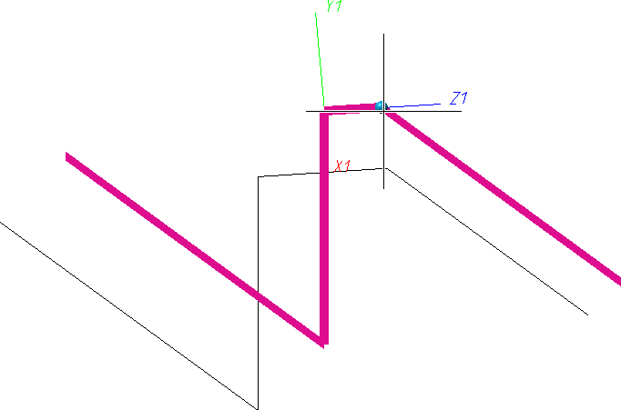
Therefore, activate the Always project points on axes checkbox. This allows you to choose the required point:
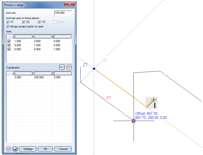
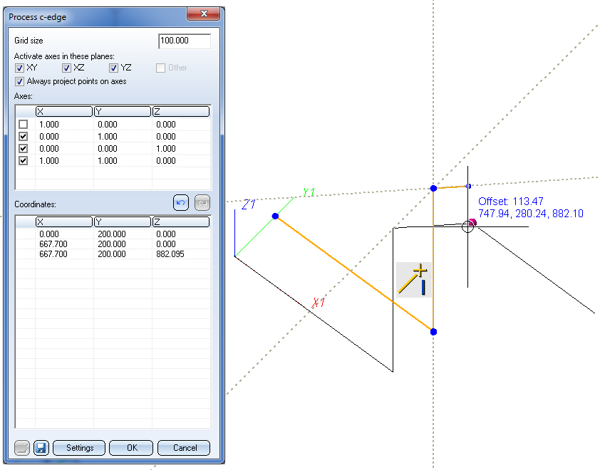
Proceed likewise to choose the next point.
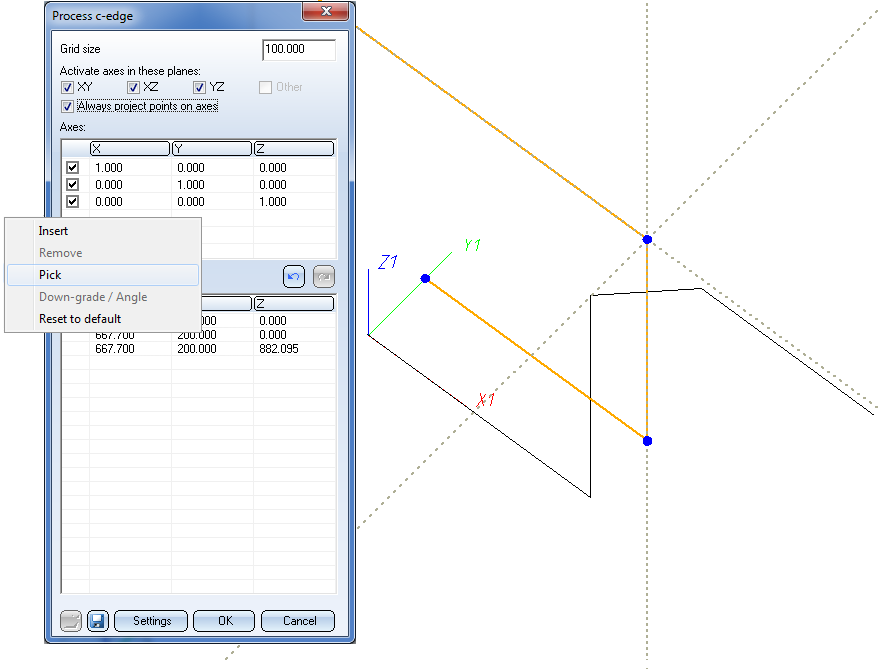
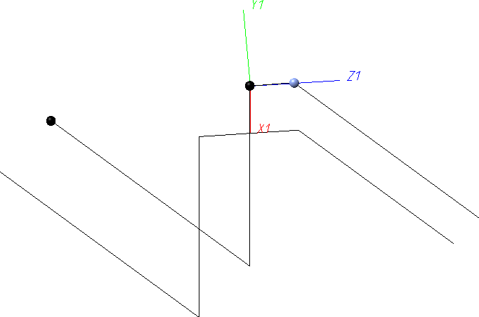
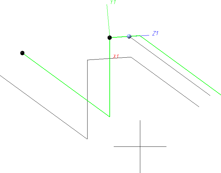
Now you will notice that there is no suitable axis to continue parallel in diagonal direction. Therefore, define an additional axis by picking it from the drawing.
First, identify the start point of the diagonal of the original guideline.
Proceed likewise with the end point of the diagonal.
If you now try to continue with the construction of the guideline, you will notice that the wrong axis will be selected as projection axis.
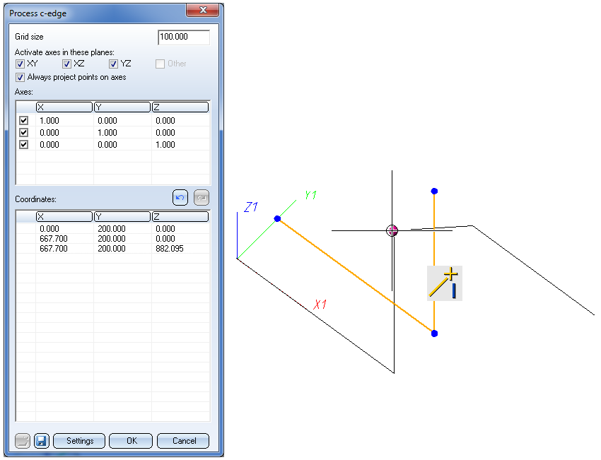
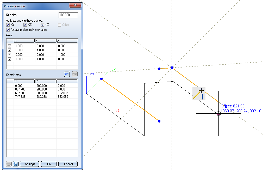
Therefore, temporarily activate the axis in X-direction. Now, the new axis that you created will be recognized as the nearest axis, and you will obtain a suitable projected point.
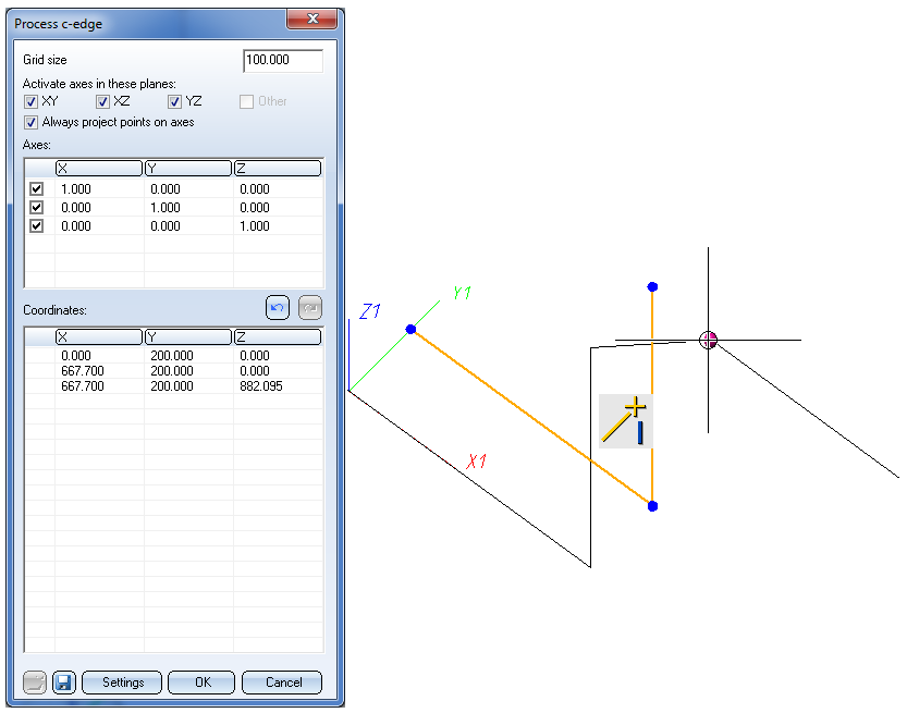
For the selection of the last point, activate the axis in X-direction again.
Click OK to close the dialogue window and complete the creation of the guideline.
 An additional tip
At this point you may ask yourself whether the end point of the diagonal section can also be placed on the same X-coordinate as on the original guideline to obtain the following result:
Therefore it will also be shown how to adjust the result of our example by modifying the route accordingly.
Step 1:
Activate the pipeline with the parallel guideline. Define a Local CS by selecting the LCS on guideline (z in edge direction)  function (Plant Engineering > Settings > Settings
  > ...) and choosing the diagonal as the reference edge.
Step 2:
Change the guideline route using the Change route  functiion (Plant Engineering > Pipeline Tools > Change > ...) and choose the corner point at the end of the diagonal with a mouse click.
Step 3:
Right-click and choose Select fixed points). Select the fixed points as shown below.
Schalten Sie dann mit der mittleren Maustaste zurück zur Verlaufsänderung.
Step 4:
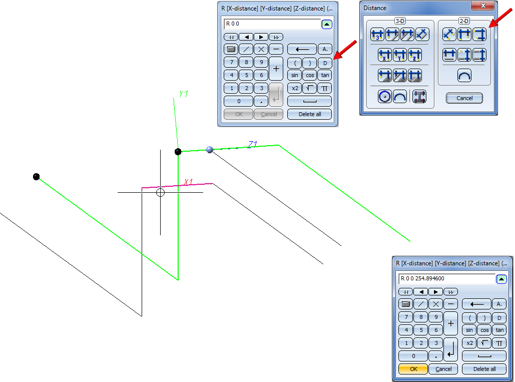
Now determine the target point. Right-click and choose Standard point selection.
Determine the target point relative to the start point of the diagonal. Use the point option Relative (R on the keyboard), press ENTER and choose the start point of the diagonal. Then, enter the value 0 for the X- and Y-distance. The Z-distance is to be taken over from the original pipeline. Therefore, click the D (Distance) button in the pocket calculator. In the Distance menu, choose Edge length and select the diagonal of the original guideline.
This example has been selected for didactic reasons. The result from Step 4, which basically represents a copy of a guideline can, of course, be achieved more easily by simply using the Copy guideline function.


Guideline Tools (PE) • Create Guideline - Settings • Plant Engineering Functions
|
© Copyright 1994-2018, ISD Software und Systeme GmbH |