Configuration Management - What's New?

Service Pack 2 2024 (V 2902)
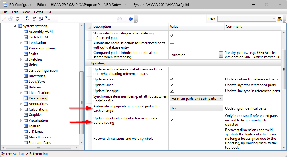
Referencing - Updating identical parts
In the Configuration Editor at System settings > Referencing, the parameters:
-
Automatically update referenced parts after each change and
-
Update identical parts of referenced parts before saving
have been added again in SP2. This allows you to choose whether all identical parts in the current drawing should be updated automatically when changing externally or internally referenced parts.
Update automatically calculated attributes before saving
For the calculation of attributes that are set to Manual / When itemising in the Configuration Editor, you can specify whether or not these calculations should be performed automatically before saving referenced parts and assemblies. The parameter Update automatically calculated attributes before saving is available in the Configuration Editor at Modelling > Part properties. Weight (§01), Surface area (§10 and §SC) and Volume (§20) are updated. The attributes Total quantity. (%06) and Qty. in assembly (%13) are not updated.
Service Pack 1 2024 (V 2901)
Time threshold for AutoQuickView
In the Configuration Editor, it is now possible to set a time threshold for the AutoQuickView display of hidden line or glass model calculations. If the threshold value is exceeded, the calculation is cancelled and the view is displayed in QuickView. Subsequent calculations then no longer start a HiddenLine or Glass model calculation, as the view is already in QuickView.
The setting is made at System settings > Visualisation > Views > Time threshold for AutoQuickView . The default setting for the time threshold is 0 seconds. This means that the AutoQuickView behaves in the same way as before and is applied to every Hidden line and Glass model calculation. In workshop drawings, a value of 0.1 to 0.5 seconds can cause the views of the individual items to be displayed "Exact" and only "large" views of the entire drawing to appear in the QuickView.
SpaceMouse®
There is a new setting in Configuration Management under System settings > Miscellaneous: Exit SpaceMouse mode by moving the mouse. If this setting is activated, SpaceMouse mode must be ended by a mouse action.
Referencing
Update identical parts
The parameters Automatically update referenced parts after each change and Update identical parts of referenced parts before saving have been removed in Configuration Editor at System settings > Referencing, as from SP1 all identical parts in the current drawing are automatically updated when externally or internally referenced parts are changed.
Referenced assemblies with referenced parts
When saving drawings with changed referenced parts, you can determine the procedure for the referenced assembly that contains the referenced part. In the Configuration Editor at System settings > Referencing > Saving changed assemblies, set the default setting for saving referenced assemblies. The default setting is Only structurally changed assemblies. If you select a different setting during a current HiCAD session, the setting from the Configuration Editor will be used again in the next session.
Additional column in the Packaging dialogue
When choosing Profile installation > New/Change > Packaging  , there is now an additional column for a user-specific attribute for the Packaging dialogue window. This attribute must be set in the Configuration Editor at Profile Installation > Packaging > User-specific attribute.
Development attributes for Steel Engineering plates
If the settings
-
Surface area calculated from development contour (§SOC)
-
Rectangular surface area of development (§S2D)
are activated in the Configuration Editor at Modelling > Part properties > Sheet Metal, then not only Sheet Metal parts will be calculated, but also Steel Engineering plates from HiCAD 2024 SP1 onwards.
Drawing Management
Documents for general documents
There are two new settings in Configuration Editor at PDM > Drawing Management > External production documents:
- Creation of external documents
This parameter determines whether external documents should only be created for the active sheet or for all sheets. This is possible as of HiCAD SP1. The default setting is Active sheet. - HELiOS attribute for HiCAD sheet names
Here you specify which HELiOS attribute the HiCAD sheet name should be assigned to. The HELiOS attribute BENENNUNG (Designation) is preset.
Managing general 3-D parts via part filter
In the Configuration Editor at PDM > Drawing Management, you can set whether general 3-D parts should also be taken into account when managing drawings.
As of SP1, the new Via filter option is available for the Manage general 3-D parts parameter. With this setting, only the general 3-D parts that meet the part filters defined in the Favourites file Steel Engineering > Drawing Management > General parts (BIM-3DPartFilter.xml) are taken into account.
Plant Engineering
Pipe length check no longer as macro
In HiCAD 2024 SP1 the pipe length check can be carried out together with the nominal width check and the structure check in a check routine during loading and saving. For this purpose, the setting Checks the entire drawing (Plant Engineering > Plant Engineering drawing check) must be activated in configuration management. By default, the check is switched off.
Insert plane flange
In the Configuration Editor at Plant Engineering > Layout plan you can define a distance between a straight pipe and the plane flange. Use the parameter Insert plane flange, with projection.
Settings for down-grade symbols
The settings for the Down-grade symbols have been changed. You can now select the unit for displaying the down-grade symbol in the Configuration Editor. You can also set the number of decimal places and the distance between the down-grade symbol and text.
Interfaces
It is now possible to specify in the configuration editor that when opening foreign formats (e.g. STEP) via Drag & Drop or double-click (in Windows Explorer), a dialogue window is no longer displayed to make changes. To do this, use the parameter Import files directly during Drag & Drop at Interfaces > Import.
Major Release 2024 (V 2900)
Part properties
Automatically calculated attributes
In the Configuration Editor, at Modelling > Part properties, you can now determine the time of the calculation for attributes that are set to Always, with the setting Automatically update calculated attributes when loading. With the default setting No, the attributes are not updated during loading. The attributes are recalculated in HiCAD if you change the part, itemise it or recalculate it with the function Update part attributes.
If you include an attribute that has not yet been calculated, e.g. the weight, in the calculation and have changed the default setting, the calculation is carried out for all parts when the drawing is loaded. This can lead to waiting times.
Parameter configuration
The default settings of the standard template for Steel / Metal Engineering have changed with HiCAD 2024. This affects the settings at Modelling > Part properties in the Configuration Editor.
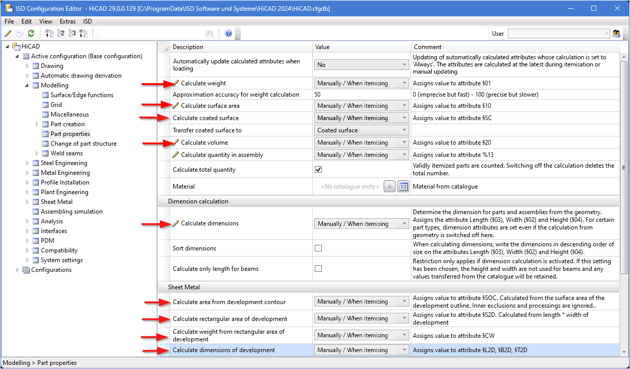
The default setting of the parameters indicated in the image below was previously Always.
The parameter configuration Steel Engineering can be selected either during installation or subsequently with the tool ParKonfigComp.exe (or ParKonfigUser.exe).
CFGDBTool.exe
If you want to transfer your individual settings from the HICAD.CFGDB file of an older version into the Configuration Editor of the new version, the CfgDbTool.exe program is available in the HiCAD EXE directory. This tool is now available in all languages supported by HiCAD.
Intersections in the Hidden Line representation
Up to now, only intersections (or collisions) found between straight lines and planes or those involving circles and cylinders were taken into account in the HiddenLine calculation. From HiCAD 2024, all collisions with analytical curves/surfaces or with Nurbs curves/surfaces are now also taken into account.
What exactly is taken into account can be defined in Configuration Management under System settings > Visualisation > Views > Hidden Line > Collision check.
Part master display by double click
Until now, double-clicking the left mouse button on a part in the drawing or in the ICN called up the Part attributes dialogue window. In the Configuration Editor at System settings > HELiOS you can now set whether the part's article master should be displayed alternatively. To do this, activate the setting When double-clicking on a part, display article master instead of part attribute mask. If the clicked part does not have an article master, the Part attributes dialogue window will be automatically displayed.
Magnetic snap-in when moving views
The alignment of views to each other or to other elements (e.g. drawing frames, title block frames and bills of materials) of a drawing sheet has been facilitated by "magnetic" snap-in. As soon as a constellation is created during dynamic shifting of a view that facilitates alignment, graphic auxiliary elements (e.g. distance arrows, alignment lines) are displayed.
If no auxiliary elements are to be displayed, deactivate the setting Allow alignment based on equal distance at System settings > Visualisation > Views > Magnetic snap-in.
Negative and positive position in identical part search
The negative and positive position of the profiles is a distinguishing criterion for the identical part search in the dispatch itemisation. For this purpose, the new attribute DWF_NEG_INSTALL has been created as a distinguishing criterion. In configuration management, it is entered as a distinguishing criterion for the dispatch itemisation at Profile installation > Dispatch itemisation > Integer attributes and is evaluated if the setting Carry out dispatch itemisation is also activated here.
Processing external drawings
As the processing of external drawings can lead to problems with the automatic drawing derivation, a processing lock has been built into HiCAD. If you still want to allow manual changes in external drawings, activate the parameter Allow processings in external drawings. You will find the parameter under Automatic drawing derivation and then Production drawing.
Processing sheet metal developments in production drawings
In drawing management, processing (e.g. applying fillets to edges) of developments in the production drawing was previously prevented. As of HiCAD 2024, the new parameter Allow processing of sheet metal developments is available in the Configuration Editor at PDM > Drawing derivation > Production drawing. The ISD default setting is No. With Yes, it is possible to process and save the development in already created drawings without marking the Sheet Metal part as changed.
If you allow processing of developments in the production drawing, no more automatic STEP, DXF data can be created for Sheet Metal parts, because the CAM data is generated directly from the Sheet Metal part.
Generate pipe spool drawing from sheet view
If pipe spool drawings are created in a sheet area of the active design and then a new pipe spool drawing is created from this sheet view, then as of HiCAD 2024 exactly those parts are taken into account in the new/updated pipe spool drawing that were also visible in the original sheet view. This means that in this case you will no longer be prompted to select the parts for the pipe spool drawing.
If, on the other hand, the pipe spool drawing is generated from the model view, then the behavior does not change and you are prompted to select the parts as before. Unless you have deactivated the checkbox Part selection before displaying pipe spool drawing dialogue in the configuration management under Plant Engineering > Isometry and Pipe Spool Drawing.
Automatic BOMs for itemised source models
Excel BOMs can now be created and managed automatically for model drawings that are itemised source models. For this purpose, the settings in the Configuration Editor at PDM > Drawing Management > External production documents have been extended by:
-
Create BOMs: With this setting you determine when Excel BOMs are to be created for selected drawings.
-
List of model drawings with external BOM: With this setting you determine for which drawings external BOMs are to be created and managed.
