Layout Planning - What's New?

Service Pack 2 2024 (V 2902)
New connection for ALUCOBOND SZ 20
There is a new option in the Connection, top list box for the ALUCOBOND Tray panel SZ 20. You can now create a Z-profile as a folded sheet for the window connection.
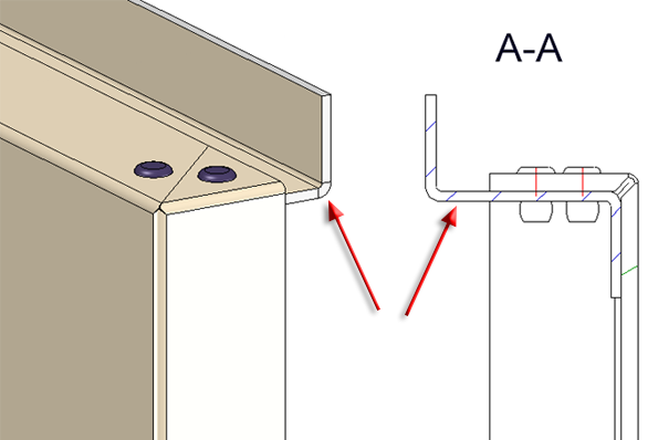
Top connection: Window with profile
Fastening for ALUCOBOND Tray panel SZ 20
The bores in the Z-profiles of ALUCOBOND Tray panel SZ 20 for fastening to the substructure are now optionally adjustable. This is useful, for example, if the bore is carried out on site. In the Extended settings for the Z-profiles of the ALUCOBOND Tray panel SZ 20 (with accessories), the option Create bores for sub-structure can now be deactivated.
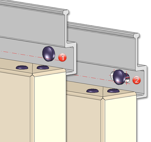
(1) Without bores for the sub-structure, (2) With bores for the sub-structure
Service Pack 1 2024 (V 2901)
Wall bracket usage for parts without a steel engineering axis
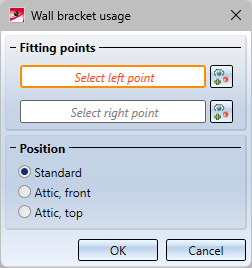
The Wall bracket usage function is now also available for parts that do not have a steel engineering axis. For these parts, the axis must be explicitly defined in the dialogue window using two points.
The dialogue windows for beams and sheets or other parts without a steel engineering axis are therefore different.
|
|
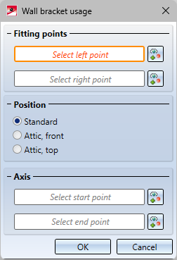
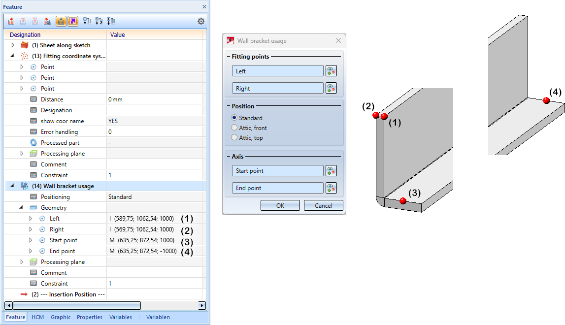
Creating your own sheets is essentially the same as creating your own beams and profiles. However, there is a difference when using wall brackets. Here, for parts that do not have a steel engineering axis, an axis must be defined via two points, which is then used in the Wall bracket function in the same way as the steel engineering axis.
In the image below, a sheet has been created along a parameterised sketch. The variable i_l has been assigned to the sheet.
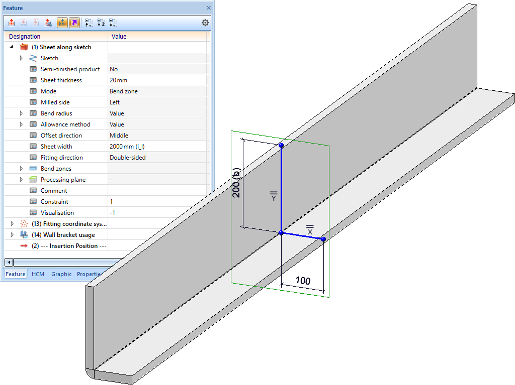
The Fitting coordinate system has then been defined using points (1), (2) and (3).
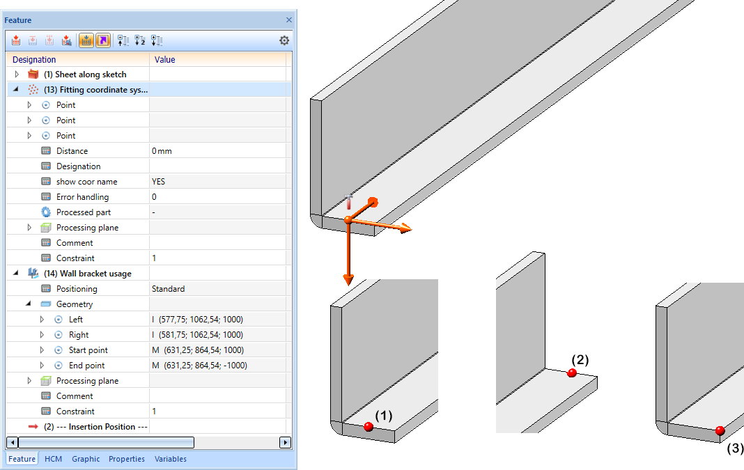
The wall bracket utilisation was then defined as shown using points (1) to (4).
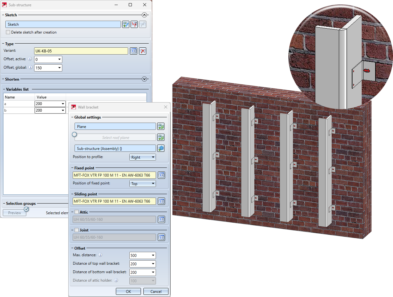
The sheet was then saved in the Factory standards > Installation planning - Parts and Processings > Sub-structure > Installation elements > ISD Example catalogue.
The image below shows a sub-structure with the sheet created above and wall brackets.
Major Release 2024 (V 2900)
Change of the structure in the docking window
In the Civil Engineering functions docking window, the functions for the Element installation, the Sub-structure and the Wall brackets have been combined and restructured under the new entry Layout planning.
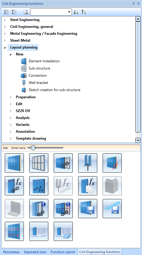
The Design Variants Flange for SZ20 and SZ20 Base point with projection can now also be found here.
Annotating installation elements
New in the Civil Engineering functions docking window at Layout planning > Annotation is the function

With this function, the installation elements of an element installation can be annotated automatically, e.g. for overview drawings.
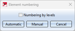
Numbering by levels
If this checkbox is activated, the numbering will be done per "level", always from the first element at the bottom left to the last element. The Y-axis determines the level direction. If the checkbox is deactivated, numbering will be done consecutively.
Automatic
With automatic numbering, the XY-plane of the active coordinate system determines the numbering sequence (first in X-direction, then in Y-direction).
Manual
Here you simply select the elements to be numbered with a mouse click.
The content of the numbering is controlled by the following annotation templates:
- EINumbering_PerLevel.ftd (for numbering by levels)
{Level of element installation numbering (part attribute)}-{Running number of element installation numbering (part attribute)} - EINumbering_Consecutive.ftd (for consecutive numbering)
{Consecutive number of element installation numbering (part attribute)}
As with the other HiCAD annotation templates, the files can be individually configured if required, e.g. with the HiCAD Annotation Editor. The files are located in the HiCAD sys directory.
Example:
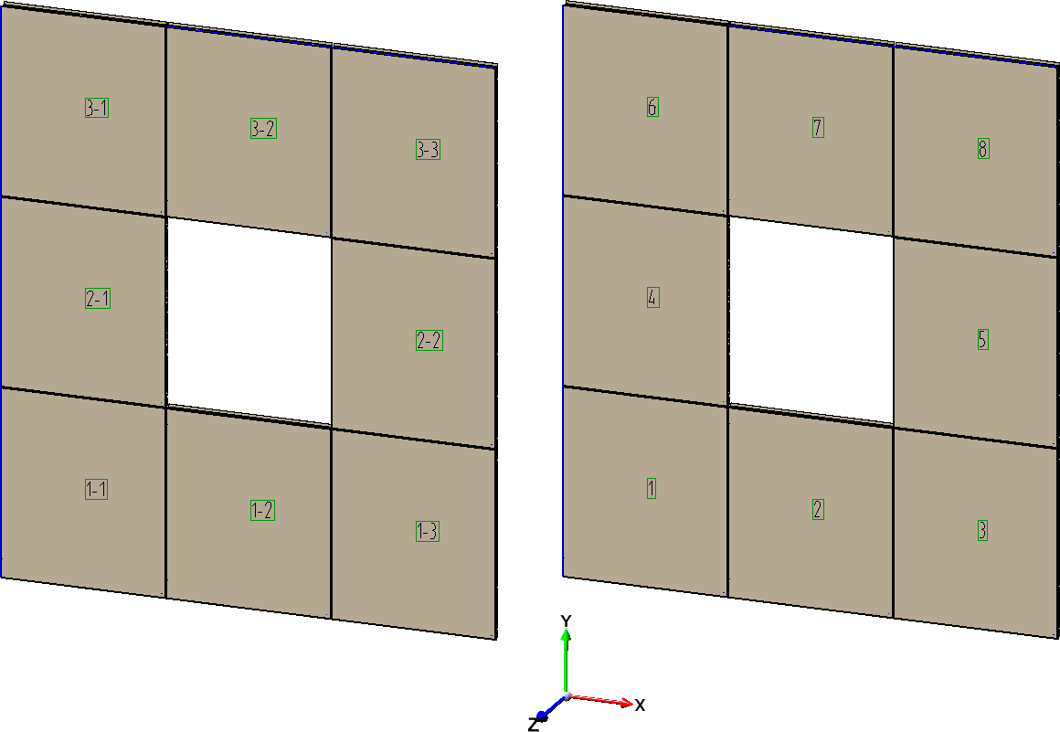
Left: Numbering by levels, Right: Consecutive numbering.
It will not be checked whether the numbered elements are identical.
