Civil Engineering functions > Layout planning
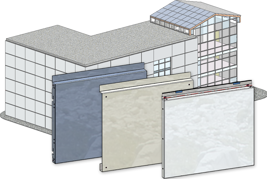
The Layout planning module is an efficient tool when it comes to assigning the same parts of a HiCAD catalogue to areas such as facades, walls, floors etc.. These can be, for example, sheet metal cassettes, glass, gratings or any other catalogue elements such as doors or window openings. The laid elements can also be suspended in or mounted on sub-structures made of various profiles, and wall brackets can be automatically generated for the sub-structure.
Layout planning thus offers everything for innovative facade planning of the entire building shells, especially functions for rear-ventilated facades.
For example, entire facades can be quickly covered with sheets and panels, e.g. ALUCOBOND® tray panels.
The layout planning functions can be found in the Civil Engineering functions docking window. If the docking window is not visible, activate it with the function  Settings > Docking windows > Civil Engineering functions in the HiCAD Ribbon.
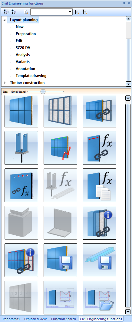
The following functions are available:
|
New |
|
|
|
With the Element installation function, cassettes and elements with a planar base surface can be conveniently placed on a sketch. |
|
|
Elements that are installed using the Element installation function often have to be suspended in or mounted to a sub-structure made of various profiles. With the sub-structure function, profiles can be placed on the lines of a sketch, similar to the element installation. |
|
|
By connecting a sub-structure with an element installation, it is possible to have the assembly of the element installation to the sub-structure automatically simulated in HiCAD. For example, drill holes as well as suitable fasteners can be created in the element installation and sub-structure. |
|
|
With this function, wall brackets can be created automatically for a sub-structure.. |

|
Sketch creation for sub-structure For some element installations it can be useful to take over the structure of the sub-structure from the finished element installation. This function generates a sketch from a finished installation, which can then be used as a basis for a sub-structure.. |
|
Preparation |
|
|
|
In order to be able to connect own parts in element installations and sub-structures with the function Connection, these must be prepared accordingly. |

|
With this function, operations can be repeated and parameterised for use with connection parameters. |

|
Wall bracket usage In order to be able to place wall brackets to match sub-structure profiles, special information must be available for the latter. This can be conveniently defined with the function Wall bracket usage. |
|
Edit |
|
|
|
With this function, parameters of a tray panel of the element installation can be transferred to other panels. |
|
SZ20 DV |
|
|
|
With this design variant, when using ALUCOBOND SZ 20-tray panels, connections with flanges can also be created for lateral connections, so that a "U" is formed. |
|
|
SZ20 base point with projection With this design variant, flanges can be attached at the bottom connection to which an S- or Z-profile or a Z-fold is riveted. |
|
Analysis |
|

|
While preparing your own parts for connection using the Connection function, it can be helpful to have the variables created by the connection generated on a test basis. |

|
This function displays the connection edges of one or more parts and installations. |
|
Variants |
|
|
|
Save variant for element installation With this function you save customer-specific installation elements as a variant. The prerequisite for this is that you have designed and parameterised the corresponding installation element and an installation coordinate system is defined for the variant. |
|
|
Save variant for sub-structure Use this function to save customer-specific sub-structures as variants. The prerequisite for this is that you have created and parameterised the geometry of the sub-structure and an installation coordinate system is defined for the variant. |
|
Annotation |
|
|
|
With this function you can annotate the elements of an element installation. |
|
Template drawing |
|
|
|
The function Template drawing allows you to automatically generate individual drawings for a selection or directly for all elements in an element installation. It is possible to generate different drawings depending on the configuration of the individual variants. |
|
|
With this function you can open the template drawings belonging to the currently selected part. |


Element Installation: Basic Procedures • Edit Installed Elements • Element Installation: Example • Sub-structure