Configuration Management - What's New?

Service Pack 2 2023 (V 2802)
Highlighting of list views
The deactivation of the parameters
at System settings > Visualisation > Views > Frame of active view only affects the active view as of SP2. If a view list is active, then the views of this list are always marked by a wider dashed frame.
Automatic data save: Higher performance
The behaviour of the automatic data save with regard to the polygon model of parts can be influenced in the Configuration Editor at System settings > Data save via the checkbox Quick data save. The checkbox is active by default. This improves the performance of the automatic data save for drawings with many parts.
Default settings changed
The following ISD default settings in the Configuration Editor have changed during a new installation (no changes during updates). The settings are independent of the selection in ParConfigComp.
- System settings > Identification > Grid angle: The grid angle when drawing lines in sketches has been changed from 15 degrees to 5 degrees..
- System settings > Annotations > Dimensioning, 3-D > Interactive dimensions > Dimension assignment: 3-D dimensions are not assigned to the active part, but to the part to which the first dimension base point belongs.
- Steel Engineering > Representation > Type of beam representation: Beams are now created in exact representation.
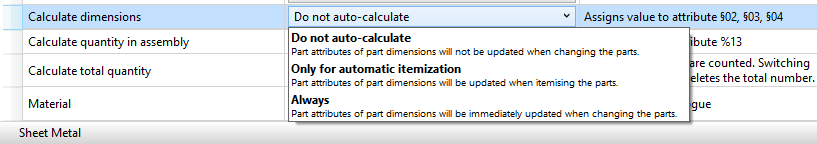
Procedure for dimension calculation
Beams
In the Configuration Editor at Modelling > Part properties there is a new parameter Calculate only length for beams. This allows the automatic calculation of the beams to be limited to the length as before. Height and width are taken from the catalogue if necessary. This parameter is deactivated in the ISD default setting. The restriction only applies if the dimension calculation is activated.
Plates
If the automatic dimension calculation (Modelliing > Part properties > Calculate dimensions) is active, length, height and width are written with the determined values. If the automatic dimension calculation is deactivated, the previous procedure applies. Length, height and width are assigned by the steel engineering functions. Length and width are sorted (Modelling > Part properties > Sort dimensions.
Production drawings for mounting assemblies
In the Configuration Editor at PDM > Drawing Management > Production drawings the new parameter Production drawings for mounting assemblies is available. With this parameter, mounting assemblies (Type: Bolted assembly) can be excluded from the production drawings if required. The default setting is Yes.
Itemisation - small text adjustments
In the Configuration Editor, the term "Itemisation mode, Standard" at System settings > Itemisation and System settings > Itemisation > Migration has been replaced by an explanatory text.
Automatic deactivation of the HCM
The HCM is automatically deactivated if sketches exceed a certain number of lines during the 3-D DXF import or during the conversion of 2-D sketches. You set this number in the Configuration Editor at System settings > Sketch HCM. The ISD default setting is 1000. Please note that if you activate the HCM constraints for such sketches, then there may be considerable waiting times..
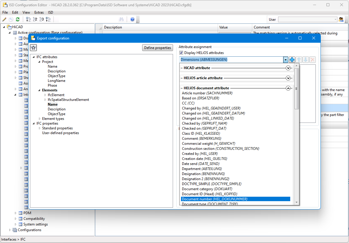
IFC attribute mapping: Display HELiOS attributes
In the attribute mapping configuration for the data transformation between IFC and HiCAD, you can also export HELiOS attributes as of Service Pack 2.
In the Configuration Editor you can find a new checkbox Display HELiOS attributes at Interfaces > IFC > Attribute mapping configuration > ISD defaults >  Define.
If this is activated, HELiOS attributes are also available for mapping in the pull-down menu of the source attributes.
You can expand and collapse corresponding overviews of the different categories of attribute types.
Transfer of LogiKal attributes to HiCAD
In addition to the item names for profiles and glass panes, the attribute assignment between LogiKal and HiCAD has been extended by some numerical and text attributes.
Transferable numerical attributes are [Glass] Acoustic Performance, [Glass] Light Transmittance, [Glass] Solar Factor and [Glass] Weight for glass panes, as well as the [Insertion] Handle height (from FFL) for profile inserts.
You can assign these LogiKal attributes to corresponding, user-defined HiCAD attributes in the Configuration Editor at Interfaces > LogiKal.
Service Pack 1 2023 (V 2801)
Units in the Configuration Editor
In the menu bar of the Configuration Editor, at Extras > Units, you can set whether the values specified there for lengths and weights are to be displayed in metric units (millimetres and kilograms) or in imperial units (inches and pounds).
Settings removed
Display of dimensional constraints of sub-sketches
To improve performance, the setting Show dimensional constraints of sub-sketches at System settings > Sketch HCM has been removed from the Configuration Editor.
OpenGL capacity
Since HiCAD no longer evaluates the setting OpenGL display list capacity at System settings > Visualisation, it has been removed from the Configuration Editor.
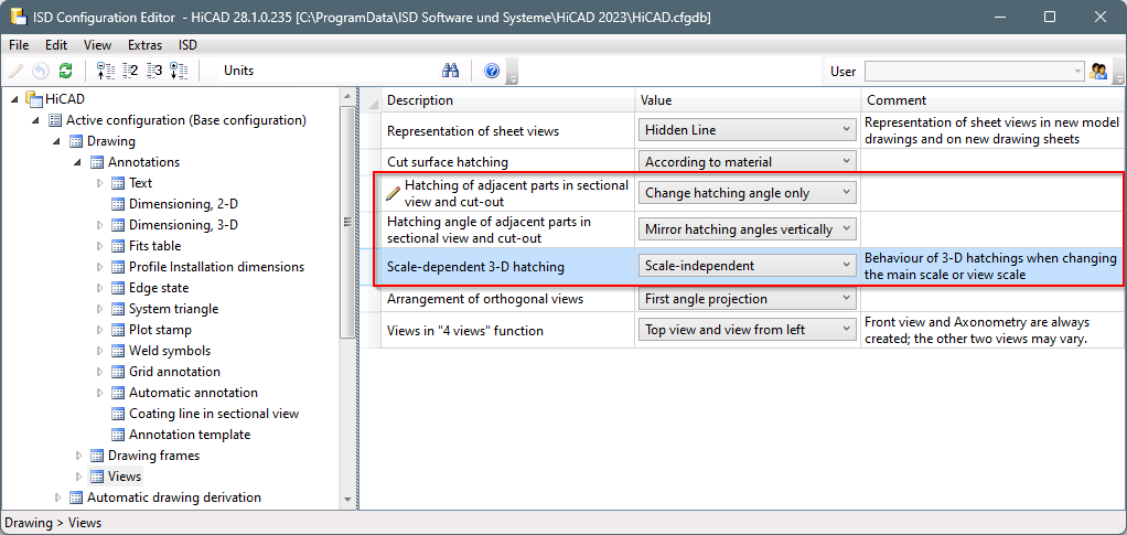
Hatching of adjacent parts in sectional view and cut-out
With the HiCAD function Hatching settings you define the delimitation of adjacent areas in sectional views and cut-outs by the hatching distance and the hatching angle. You set the default for new drawings in the Configuration Editor at Drawing > Views.
In order to combine the hatching settings in the Configuration Editor, the option Scale-dependent 3-D hatching (previously System settings > Visualisation) is now also available at Drawing > Views.
Dimension calculation - Sorting the attributes Length, Width, Height
From HiCAD 2023 SP1 it is possible to sort the dimension attributes (Length ($03), Width ($02) and Height ($04)) of the automatic dimension calculation by size, i.e. the largest value is assigned to the length, the smallest to the height. To do this, the new checkbox Sort dimensions must be activated in the Configuration Editor at Modelling > Part properties. By default the checkbox is inactive.
Configuration of the graphic display
The display, e.g. when working with sketches, when lengthening sheets or filleting, can be configured. At System settings > Identification you can set the Text colour, Text background colour, Display height and Line colour for the preview dimension display.
Itemise parts by part filters
In the Itemise parts function, the filters for automatic part annotation can now be used for annotation templates. In connection with this extension, the setting of the filters in the Configuration Editor has been moved. You can find the settings from SP1 at Drawing > Annotations > Annotation template.
Automatic conversion of the "old" itemisation with default favourites
The conversion of earlier itemisations (before HiCAD 2018) into the HiCAD standard itemisation can now also be carried out automatically, i.e. without displaying the itemisation dialogue. For this purpose, the checkbox When switching to the itemisation mode 'Standard', use the stored default settings is available in the Configuration Editor at System settings > Itemisation > Migration.
Check Sheet Metal parts for part orientation
For Drawing derivation you can check whether a particular Sheet Metal part has a part orientation. To do this, open the Configuration Editor, go to Automatic drawing derivation > Production drawing and activate the checkbox Check part alignment for Sheet Metal parts.
Isometry and pipe spool drawing: Switch off symbol alignment
From HiCAD 2023 SP1 it is possible to switch off the automatic alignment of the symbolic representation of parts in the Configuration Editor at Plant Engineering > Isometry and Pipe Spool Drawing > Align symbolic representations.
Major Release 2023 (V 2800)
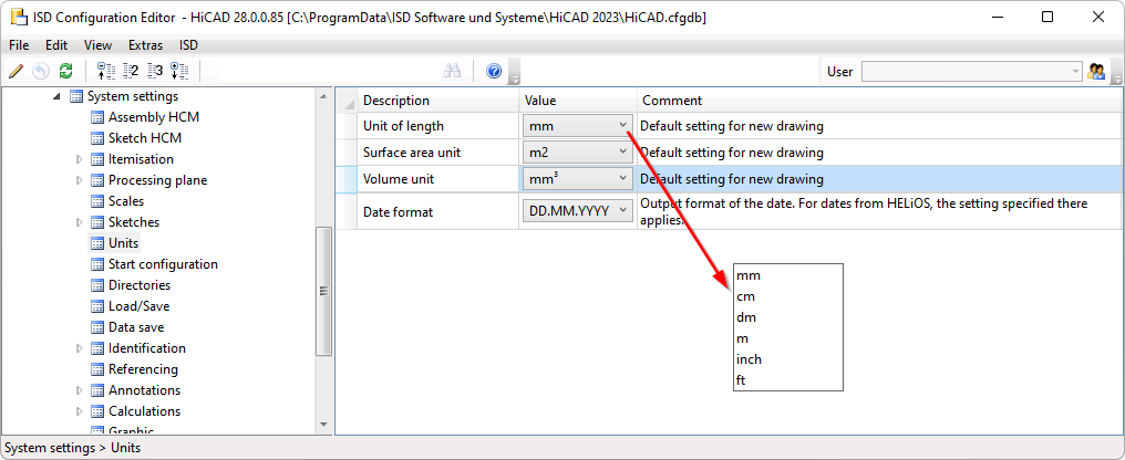
Free selection of length units in drawings
The previous version HiCAD 2022 only supported drawings with the unit of length millimetre. From HiCAD 2023 onwards, the unit of length can now be selected in the Configuration Editor at System settings > Units > Unit of length. This means that it is now also possible to design in non-metric units.
Please note the following:
The settings selected at System settings > Units only apply to newly created drawings. These settings cannot be changed in the drawing itself.
Sketch technology - Distance/angle grid presettings
The value for the angle grid when drawing planar sketches and 3-D sketches can now be preset in the Configuration Editor - at System settings > Identification in the Grid section.
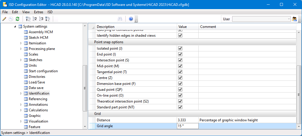
In this context, the preset for the distance grid has also been moved to this area.
Please note that the specified grid settings not only apply to the sketch technology, but also to other functions that use distance and angle grids.
Formulas, mixed numbers and units in point inputs
In the numerical point options, the numerical values required for the point option can be entered directly in one step, e.g. relative coordinates. If you now enter formulas, mixed numbers and units, e.g. (a+b), 1/2, 1 3/4" + 12.5 mm, it is essential to observe the setting in the Configuration Editor at System settings > Miscellaneous > Pocket calculator.
- Space: With this setting, the various entries must be separated by spaces. If formulas, mixed numbers or mixed units are used, they must not contain spaces. This is the default setting.
- Semicolon: If you want to use formulas etc. with spaces, then you must select this setting. The different entries must then be separated by a semicolon ;.
Drawing derivation
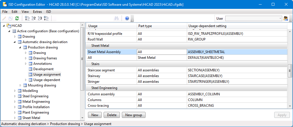
New usage for Sheet Metal assemblies
For Sheet Metal assemblies, i.e. assemblies with a Sheet Metal part as the main part, a new usage is available: Sheet Metal Assembly. The Factory standards > Usage catalogue has been extended accordingly. For assemblies with this usage, usage-dependent configurations can be used for the drawing derivation, which are managed in the Configuration Editor as for other usages. By default, the ASSEMBLY_SHEETMETAL configuration is predefined for assemblies with the usage Sheet Metal Assembly.
Production and mounting drawings - Drawing frames
As of HiCAD 2023, two additional parameters are available for production drawings in the Configuration Editor under Automatic drawing derivation> Production drawing > Drawing frames.
- Use frame
This checkbox determines whether the frame should be offered for selection in the Drawing derivation dialogue or not. The ISD default setting is yes, i.e. the checkbox is active.
- Automatic determination of geometric data for the drawing frame
If this checkbox is active, the geometric data of the frame including the usable area will be calculated automatically.
For each drawing frame you can define
- the distance of the insertion point from the centre of the frame,
- the size of the usable area (frame height / frame width) and
- the size of a blocked frame area (for the title block, BOMs or comments)
The following settings have been added to place the drawing frame exactly in the sheet:
- Horizontal distance of the upper left point to the inner frame
- Vertical distance of the upper left point to the inner frame
- Total height of the figure
- Total width of the figure
These settings help position the inner frame within the outer frame.
Analogously, the parameters listed above are also available for mounting drawings under Automatic drawing derivation> Mounting Drawing > Drawing frames.
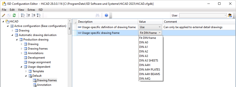
Show drawing frame
When selecting the drawing frame of production drawings under Automatic drawing derivation > Production drawing > Usage-dependent > Template or Default, the DIN name will be displayed in a ComboBox as of HiCAD 2023.
Output of PDF data in black and white
PDF files can now also be created in black and white. For this purpose, the settings in the Configuration Editor at PDM > Drawing Management > Externalproduction documents have been extended by the entry Monochrome PDF data.
Workflow when creating general documents
As with production drawings, mounting drawings and customer drawings, it is now also possible to select when general documents in DXF, DWG and PDF format are to be created. To do this, the setting in the Configuration Editor at PDM > Drawing Management > External production documents > PDF files for general documents has been extended by the options
- Upon Checkup and Release,
- Upon creation and update, and
- Upon Release.
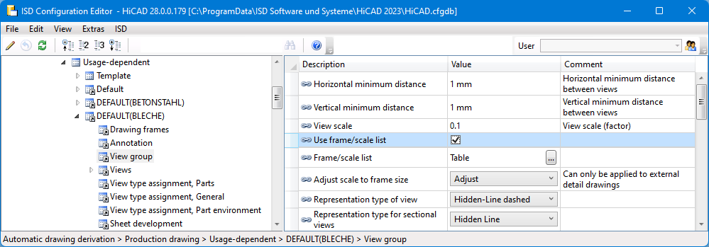
Using Frame/scale lists
The lists for drawing frames and view scale that you create with the new function Frame/scale list are only taken into account during drawing derivation if the checkbox Use Frame/scale list is active for the respective usage type in the Configuration Editor at Automatic drawing derivation > Production drawing > Usage-dependent > .... > View group is active. In the dialogue of the drawing derivation the option Drawing parameters: From configuration must then be active.
If a frame/scale list has been created in HiCAD for a purpose, it is displayed in the Configuration Editor at Frame/scale list  . It is not possible to change the list here.
Updating of part attributes
The settings for updating part attributes have been implemented uniformly for all affected attributes in the Configuration Editor. You can find the settings at Modelling > Part properties.
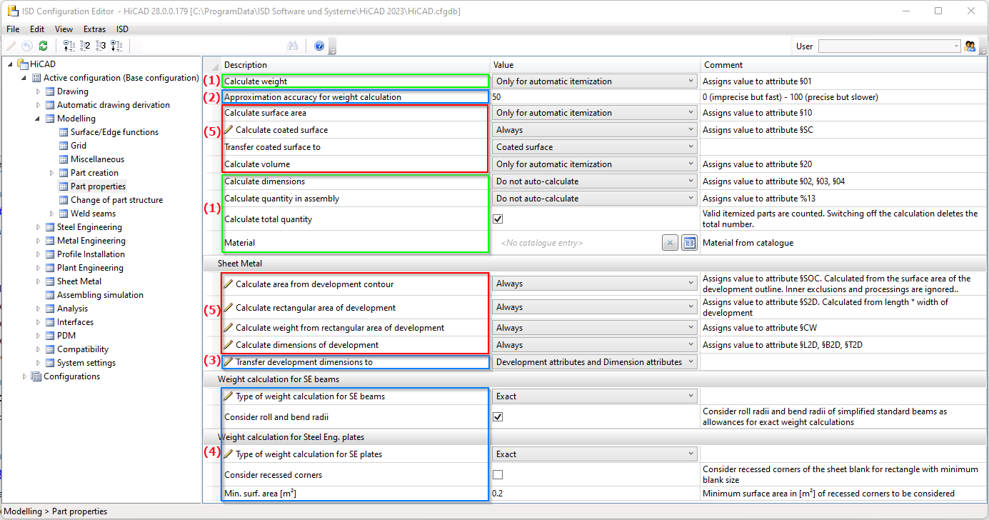
- (1) Already existing settings
- (2) Settings from the directory System settings > Calculations > Approximation accuracy for weight calculation
- (3) Settings from Sheet Metal > Sheet development > Transfer development dimensions to
- (4) Settings from Steel Engineering > Weight calculations
- (5) New parameters and new attributes (§SC, §SOC, §S2D, §CW)
Dimension calculation and alignment
Until now, automatic dimension calculation was only possible for assemblies. As of HiCAD 2023, this is also supported for 3-D parts. For this purpose, the calculation must be activated in the Configuration Editor at Modelling > Part properties > Calculate dimensions.
If the dimension is to be displayed in the drawing in HiCAD, then activate this at System settings > Visualisation > Show dimensions of the active 3-D part.
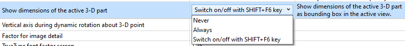
If the sheet is to be calculated instead of the sheet development, then the setting Development attributes must be selected for Modelling > Part properties > Transfer development dimensions to.
Part-related status check
Since the Part-related status check located under System settings > Miscellaneous in the Configuration Editor is no longer needed, it is no longer available as of HiCAD 2023.
Edge state - Dimension unit
The dimension unit selected in the Configuration Editor at Drawing > Annotations > Edge state is used to display the edge state. This can be selected independently of the dimension unit of the drawing.
Selection of bracket type for the 2nd dimensioning figure
The 2nd dimensioning figure was always marked with round brackets in 3-D until now. As of HiCAD 2023, the bracket type can now be selected. The default setting can be defined in the Configuration Editor at System settings > Annotations > Dimensioning, 3-D.
2-D DXF/DWG import and export options
The favourite for the default setting for 2-D DXF/DWG exports, e.g. of sheet metal developments, can be set in the Configuration Editor at Interfaces > Export > 2-D DXF/DWG. You can create the favourites when exporting from HiCAD by editing the ISD default settings.
User libraries
The functions for part and macro libraries are no longer available in Ribbon Drawing for new installations from HiCAD 2023. Existing customers who want to continue using their existing libraries can switch on the functionality in the Configuration Editor at Compatibility > User library up to HiCAD 2022 by activating the corresponding checkbox.
PDM setting removed
To avoid changes, the settings at PDM > Drawing Management >
- Delete item numbers of project-independent parts (Default =Yes) and
- Itemisation of locked parts (Default = Only project-independent part masters )
have been removed from the Configuration Editor.
HiCAD specific HELiOS settings moved to the Configuration Editor
HiCAD manages some attributes itself, which previously had to be defined in the HELiOS Options on the Database tab.
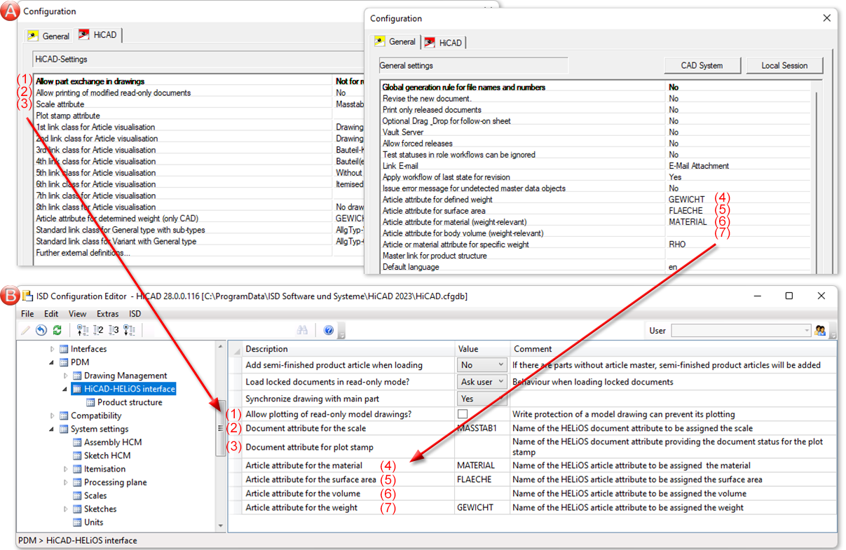
A: up to HiCAD / HELiOS 2702, B: as of HiCAD / HELiOS 2800
Plant Engineering - ROHR2 interface
In Plant Engineering, the part name of the pipeline was previously used as the file name when generating NTR files via the ROHR2 interface  . As of HiCAD 2023, the file name can be configured flexibly via HDB files. For this purpose, the following parameters are available at Anlagenbau > ROHR2 in the ISD Configuration Editor:
- Configuration of NTR file name (without HELiOS) and
- Configuration of NTR file name (with HELiOS)
The files ICN3D_DESIGNATION and ICN3D_ DESIGNATION_DB are used as ISD default settings. These are the HDB files which are also used for the display of the column Designation of the ICN window 3D Part Structure. This means that the part number of the pipeline is used as the file name by default or - if this is not available - the part name.
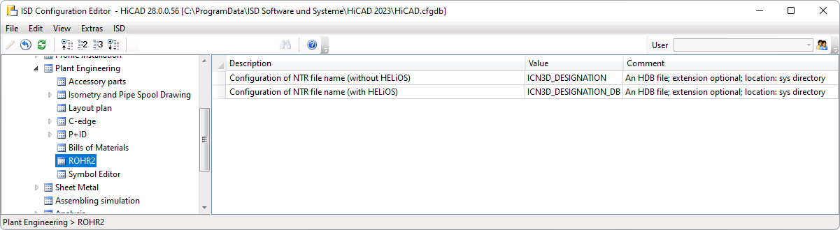
Detailed information can be found in the section Plant Engineering > Evaluation > ROHR2 interface.
LogiKal Interface - Transfer of Text Attributes to HiCAD
When importing LogiKal items (called "Positions" in LogiKal), certain LogiKal text attributes can be specifically assigned to certain HiCAD attributes. The setting is made in the Configuration Editor at Interfaces > LogiKal.
Support of IFC 4 Addendum 2
HiCAD 2023 supports the IFC 4 Addendum2 data format for IFC import.
![]() Important:
Important:
Note that as of HiCAD 2023, when importing IFC files, the IFC version specified in the Configuration Editor under Interfaces > IFC > Interface version is no longer evaluated. The version will automatically be detected during import. When exporting IFC files, however, the parameter will still be evaluated.
