When creating an isometry or pipe spool drawing, HiCAD automatically aligns the symbolic representations of the parts.
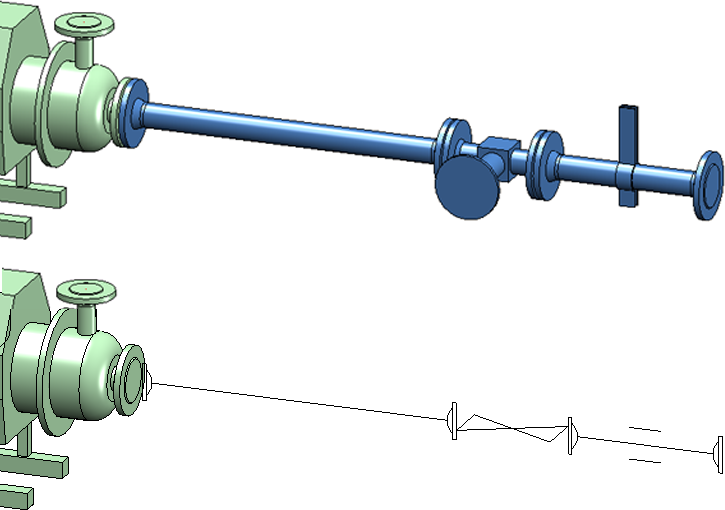
Here is the example of the symbol of a valve installed between two flanges:
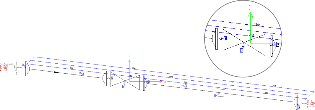
This usually looks like this in the isometry:
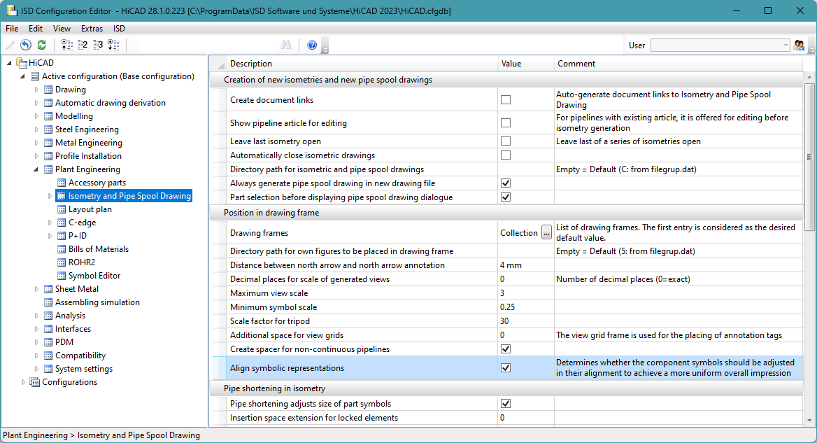
Until now, there was no way to bypass this automatism. As of HiCAD 2023 SP1, it is possible to disable this automatism in the Configuration Editor at Plant Engineering > Isometry and Pipe Spool Drawing > Align symbolic representations.
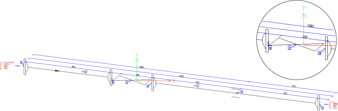
If the checkbox is deactivated, the result in the above example changes as follows:
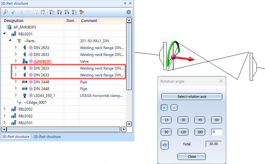
As a rule, you should leave the automatic symbol alignment switched on (ISD default setting).Exceptions can arise in individual cases, for example, if the symbol of a valve is to reflect the angle of its installation. In this case, you must manually adjust the symbol alignment in the layout plan. Please note that symbols are preferably rotated in groups in layout plan as well. So you may have to temporarily lock parts against editing, as shown in the following figure for the two flanges in the ICN.


Generate Isometry / Pipe Spool Drawing (PE/Iso) • Isometry and Pipe Spool Drawing (PE/Iso) • Isometry/Pipe Spool Drawing Functions for the Layout Plan