3-D - What's New?

Service Pack 2 2023 (V 2802)
Cams and cam processings
The cam creation creates cams on one part and slots (holes) in which these cams fit on another part. In doing so, you can specify how the cams and corresponding slots should look and how they should be arranged along the selected parts. The following functions are available as of HiCAD 2023 SP2:
|
|
With this function, a part is provided with cams. |
|
|
Cam processing
|


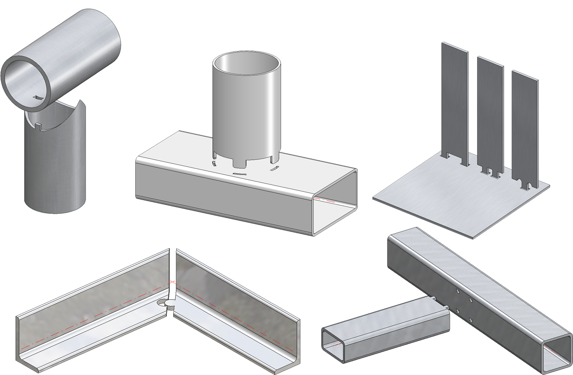
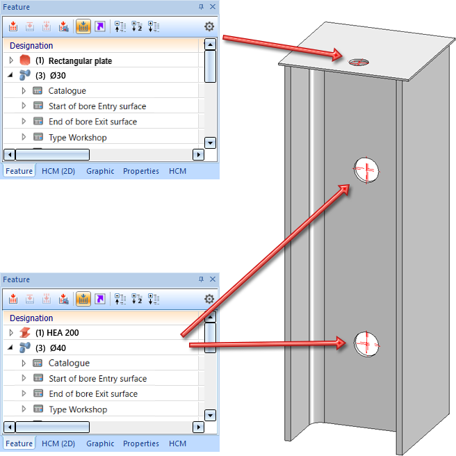
In contrast to the previous design variants to cam connections, the new functions cover significantly more practical cases and are suitable for a fully referenced working method. For example, individual cams can be placed freely here, the cams can also be distributed unevenly and they can have different edge distances on the sides. Furthermore, not only sheet metal is supported but cams can be applied to almost all types of parts - also on thin-walled solids.
The image shows different cams and the corresponding cam processings.
Part orientation and dimension alignment
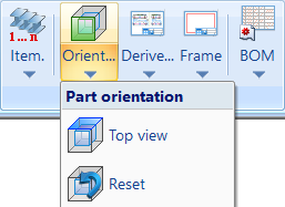
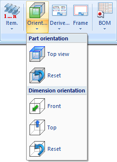
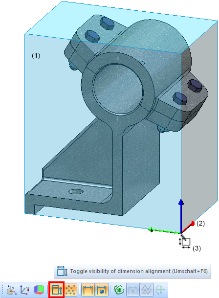
The part orientation functions have been extended. With the functions under Drawing > Orient... > Part orientation can now be used to set or reset the part orientation of multiple parts one after the other without having to call the function again.
After calling the Front view  or Top view
  function, first select the part whose orientation you want to change and then the desired plane for the front view or top view. The same functions (right mouse button) are available for the determination of the plane as for the determination of processing planes. If the dimension alignment display is also active, the enveloping cube and the orientation symbol will be updated immediately. You can then change the orientation of further parts or correct the orientation directly by selecting the previously selected part again. You can terminate the function with the middle mouse button.
The corresponding functions in the context menu apply only to the active part and are automatically terminated.
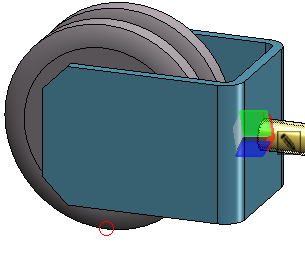
In addition, the display of the part orientation has been extended. If the orientation display is active, the orientation of the part will be indicated by a space cube and an additional symbol for the source of the orientation.
|
Meaning of the annotations |
|
|---|---|
|
|
The orientation corresponds to the part coordinate system. |
|
|
The orientation results from the bearing bar direction (only for gratings DIN 24537). |
|
|
The orientation results from the processing direction. |
|
|
The orientation was set manually. |

|
The orientation results from the part coordinate system of the assembly main part. |

|
The orientation results from the bearing bar direction of the assembly main part (only for gratings DIN 24537). |

|
The orientation results from the processing direction of the assembly main part. |
|
|
The orientation of the assembly main part was set manually. |


During the calculation of dimensions, the bearing bar orientation of gratings is assigned to the Length attribute ($03). The bearing bar orientation is ignored in the calculation of dimensions if the direction is set manually for the grating. This concerns the following cases
- The dimension direction is set.
- The part orientation is set.
- The processing direction is set.
As with the part orientation, the bearing bar orientation is also taken into account when annotating the dimension orientation.
|
|
The dimensions are current, the dimension orientation results from the bearing bar direction (only for gratings DIN 24537). |

|
|
The dimensions are current, the dimension orientation results from the bearing bar direction of the assembly main part (only for gratings DIN 24537). |

Dimension calculation of beams and Steel Engineering plates
Beams
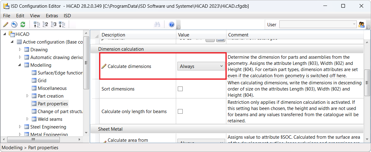
If the automatic calculation of dimensions is active in the Configuration Editor under Modelling > Part properties, then as of SP2 the dimension calculation can be restricted via the checkbox Calculate only length for beams. If the checkbox is active, only the length is determined by the automatic calculation of dimensions when it comes to beams. This means that any values for width and height from the catalogue are retained.
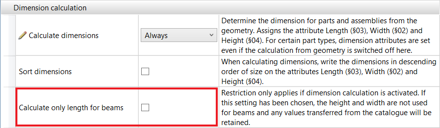
By default, the checkbox is inactive.
Steel Engineering plates
If the automatic calculation of dimensions is activated in the Configuration Editor, then length, height and width are calculated and assigned to the attributes Length ($03), Width ($02) and Height ($04).
If the automatic calculation of dimensions is deactivated, then length, height and width are assigned by the Steel Engineering functions. Length and width are sorted. This means that the largest value is assigned to the length.
Dimensioning
Changed default setting for dimension assignment
The ISD default setting for the dimension assignment has changed. As of SP2, 3-D dimensions are assigned by default to the part to which the first dimension base point belongs. The default setting can be changed in the Configuration Editor under System settings > Annotations > Dimensioning, 3-D > Interactive dimensions. The changed default setting applies to new installations only.
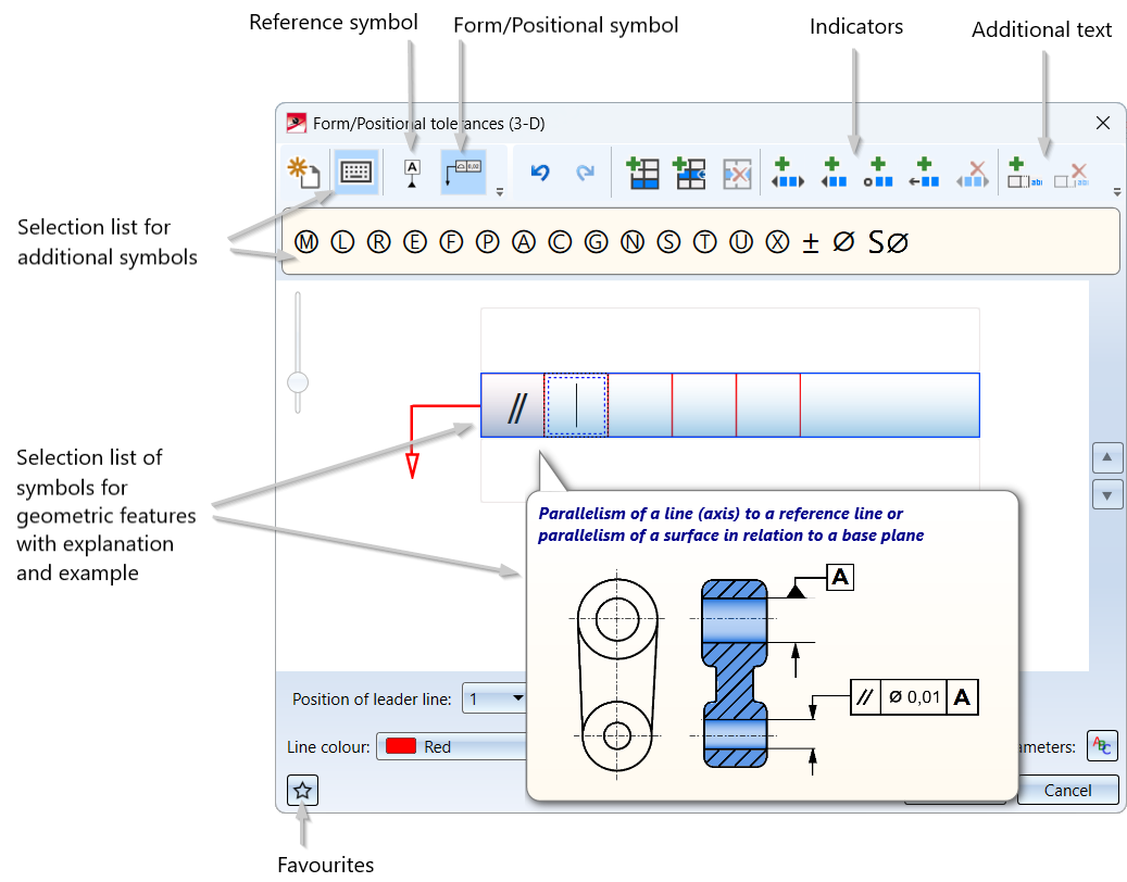
New dialogue for form/positional tolerances
The functionality for generating form and positional tolerances has been completely revised.
With the new Form/Positional tolerances (3-D)  function, tolerances with reference symbol (DIN EN ISO 5459) as well as form/positional symbols (according to DIN EN ISO 1101 and 14405-1) can be conveniently created.
The previous functionality Form/Positional tolerances  is still available in the menu under 3-D Dimensioning + Text > Symbols > Form/Pos. If a drawing contains tolerances that were created with this function, the "old" dialogue will be displayed for editing these tolerances.
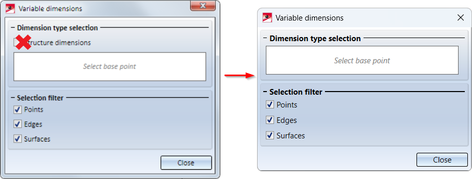
Variable dimensioning - Removal of structure dimensions
Previously, variable dimensioning could also be used to generate structure dimensions, although the waiting times here were significantly higher than for the corresponding functions in the Parallel, Direct, Angle and Arc function groups in the 3-D Dimensioning+Text ribbons.
For this reason, the creation of structure dimensions with the Variable dimensioning  function is no longer possible as of SP2.
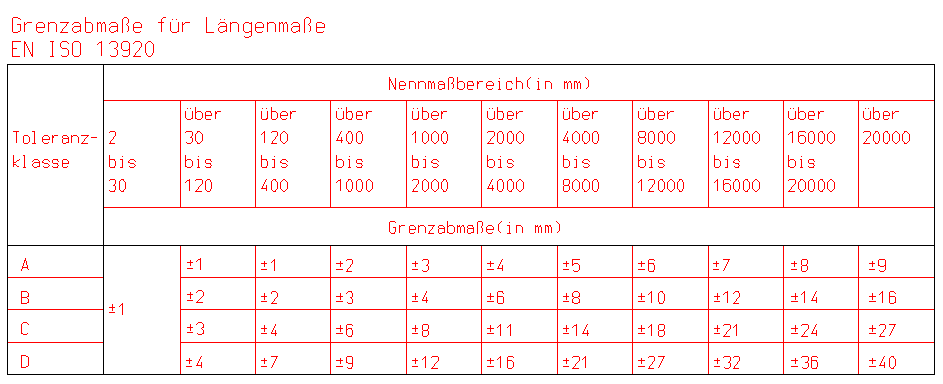
Extension of the dimension tables
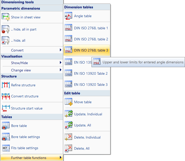
As of SP2, additional functions are available under 3-D Dimensioning+Text > Tools > Extras in the Further table functions menu:
|
|
DIN EN ISO 13920 Table 1 - Limit dimensions for linear dimensions |
|
|
DIN EN ISO 13920 Table 2 - Limit dimensions for angular dimensions |
|
|
DIN EN ISO 13920 Table 3 - Straightness, flatness and parallelism tolerances |


In addition, the tooltips in the menu have been revised and are now more expressive, e.g.
Views
Transfer part representation in view
In addition to the "normal part properties, parts can also be assigned to properties that apply only to a specific view. You assign these view properties of parts with the functions under Properties > Properties in view of the context menu for parts. In addition, individual edges of parts can be shown/hidden on a view-by-view basis using the Views > Properties > Elements function.
With the new Transfer part representation in view  function, the above-mentioned view properties of a part can be transferred to other views as of SP2. The dialogue window shown in the image is displayed for this purpose. The image shows the ISD default setting.
The function is only available in the context menu for 3-D views. Right-click on a view frame or on the name of a view in the ICN.
The dialogue depends on whether an individual view is active (1) or multiple views are selected in the ICN (2) when the function is called.
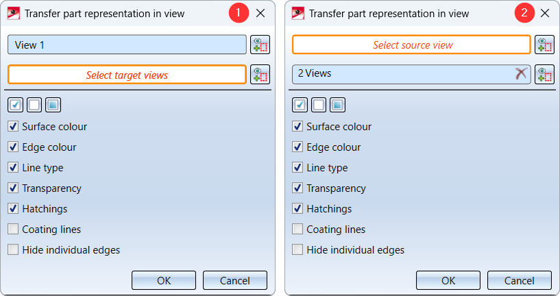
Individual view
If an individual view is active, then this view is the initial view. The name of the view will be displayed in the dialogue. To change the initial view, click on the  symbol. If the initial view is correct, select the target views, i.e. the views for which the properties of the initial view are to be applied. If an already selected target view is selected again, it will be removed from the selection list.
Multiple selection
If multiple views are selected, then these are the target views. If you want to add or remove target views, click on . When the target views are selected, select the initial view in the drawing by clicking the view frame.
After selecting the initial and target views, select the properties to be considered. To do this, activate/deactivate the corresponding checkboxes. You can also use the following buttons for selection:
 Activating all checkboxes
 Deactivating all checkboxes
 Activating the default settings
Only when you click OK, the transfer will be started and executed.
Highlighting view lists
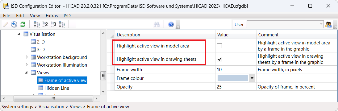
As of SP2, disabling the view marking in the Configuration Editor only affects the active view. If a view list is active, i.e. at least one view is highlighted in blue in the ICN, then the views in this list will always be marked by a wider dashed frame.
This affects the parameters
- Highlight active view in model area and
- Highlight active view in drawing sheets
under System settings > Visualisation > Views > Frame of active view in the Configuration Editor.
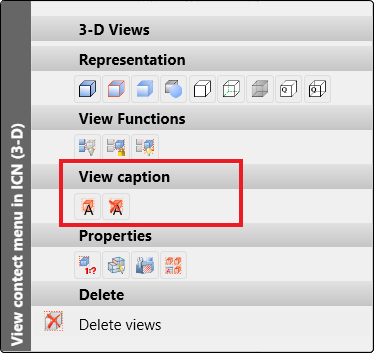
View captions - Multiple selection
As of SP2, the functions
 Create/edit/delete view caption(s) and

support multiple selection of views. This means that if multiple views are selected in the ICN, the functions act on all selected views. For example, the orientation of multiple views can be changed in one step or the caption can be hidden.
When using the Create/edit/delete view caption(s) function, note the following:
If multiple views are selected in the ICN when the function is called, the View designation is greyed out, since it generally does not make sense to give multiple views the same designation.
If none of the selected views has a caption, then all views will automatically receive a caption. The caption of the individual view can be further edited afterwards.
If at least one of the selected views already has a caption, the existing captions can be changed. Views without a caption initially remain without a caption. By activating the Show caption checkbox, however, captions can also be created and further edited for these views.
The functions are also available in the context menu when a multiple selections are made in the ICN.
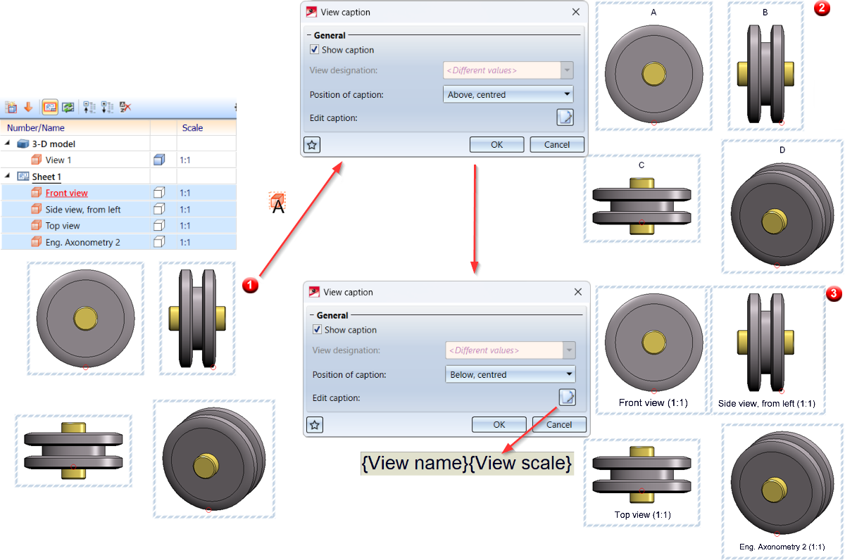
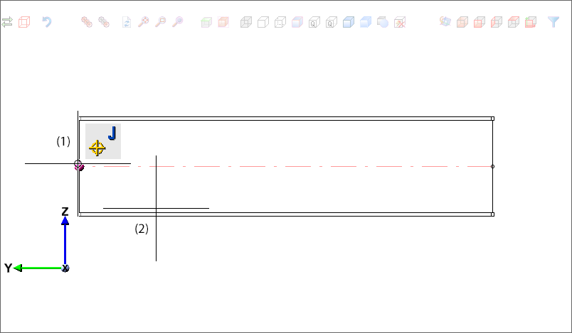
Example:
In the image 4 views - all without caption - have been marked (1). If the Create/edit/delete view caption(s) function is then called, all views receive a caption - here the view designation (2). If the position of the caption is now changed and edited as shown, the orientation and caption of all selected views will be changed (3).
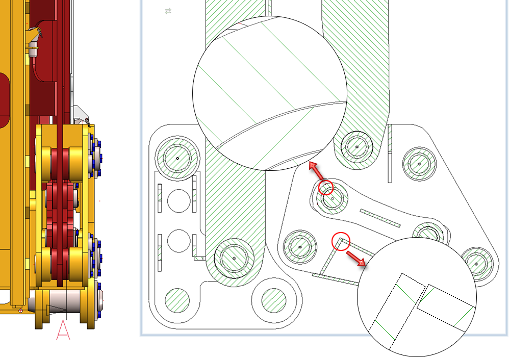
Sectional/detail views, cut-outs - hatching of adjacent parts
Since HiCAD 2023 SP1, it has been possible to define in the hatching settings of the drawing how neighbouring parts are to be visually separated from each other in a sectional view. This can be done by rotating the hatching angle or by vertical mirroring. Previously, parts had to be contiguous without gaps for them to be considered adjacent. As of SP2, smaller gaps between parts are now also possible. This means that the visual borders also apply to "almost neighbours".
Sketches
Transform/clone sketch elements - isolated points
When transforming and cloning sketch elements and isolated points, isolated points were previously not considered if the elements were selected via a rectangle. As of SP2, isolated points are now also considered for this selection type. This affects the following functions in the function groups Sketch > Transform and Sketch > Clone:
|
Transform |
Clone |
|---|---|
|
|
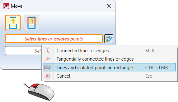
 Move sketch elements


The context menu of the line/point selection has been adjusted correspondingly.
Revision of the Move + Rotate and Rotate functions
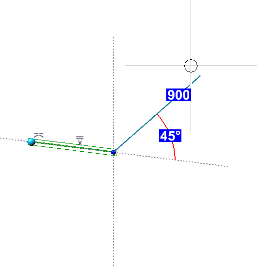
The Rotate sketch elements  function has been revised. Here the input of the rotation angle in the dialogue window is omitted.
![]()
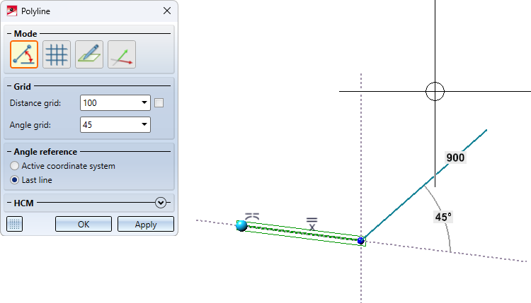
As of SP2, after selecting the line element to be rotated, the rotation is determined as follows:
- Planar sketches
HiCAD requests the selection of the rotation point and another point. The angle to the X-axis can then be determined dynamically with the cursor on an angle grid.
New in the context menu is the Angle reference  function. This function does not determine the rotation angle to the X-axis, but to a line between the rotation point and a second point.
- 3D sketches
After the direction has been determined, the angle on an angle grid can be determined dynamically with the cursor. If the Angle reference function is selected here, the perpendicular is rasterized from the selected point to the selected axis. The angle is then referenced to this line.
By tapping the cursor with the left mouse button, the rotation is applied directly.Instead of dynamically determining the angle of the rotation, it can also be entered explicitly in the HiCAD calculator. To do this, press the space bar, enter the desired angle and press OK. After the rotation has been executed, the dialogue window will remain open so that further lines can be rotated directly.
These changes have also been incorporated into the Move and rotate sketch elements  functions.
![]()
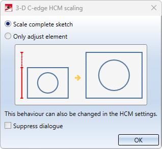
Automatic scaling of planar sketches
Automatic scaling of sketches when setting HCM constraints has been optimised further. If the first length, distance or radius constraint is assigned to a sketch, it is checked whether angle constraint (also aperture angles) have already been assigned to the sketch. If so, the 3-D C-edge HCM scaling dialogue window will be displayed.
also see Sketch HCM
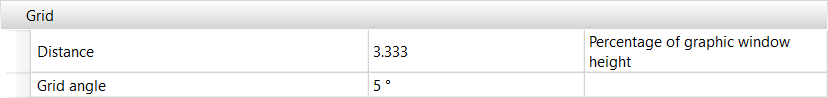
Sketch technology - Grid angle
The ISD default setting for the grid angle has changed. As of SP2, the default setting for the grid angle in the Configuration Editor under System settings > Identification > Grid is 5°. Note that these grid settings apply not only to the sketch technology, but also to other functions that use distance and angle grids. The changed default setting applies to new installations only.
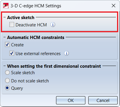
Deactivate HCM for active sketch
The automatic setting of HCM conditions for sketches can now also be switched off on a sketch-by-sketch basis, i.e. for the active sketch. This can improve performance for sketches with many lines. For this purpose, the HCM settings for sketches have been extended accordingly.
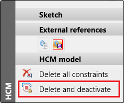
Alternatively, you can also use the function in the context menu of the ICN.
If the active sketch already contains HCM constraints when you deactivate it, the following message appears:
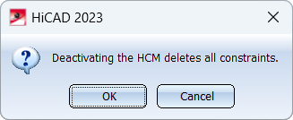
When you click OK, all constraints of the sketch will be deleted.
If the HCM is disabled, the HCM functions in the Sketch Ribbon will be greyed out.
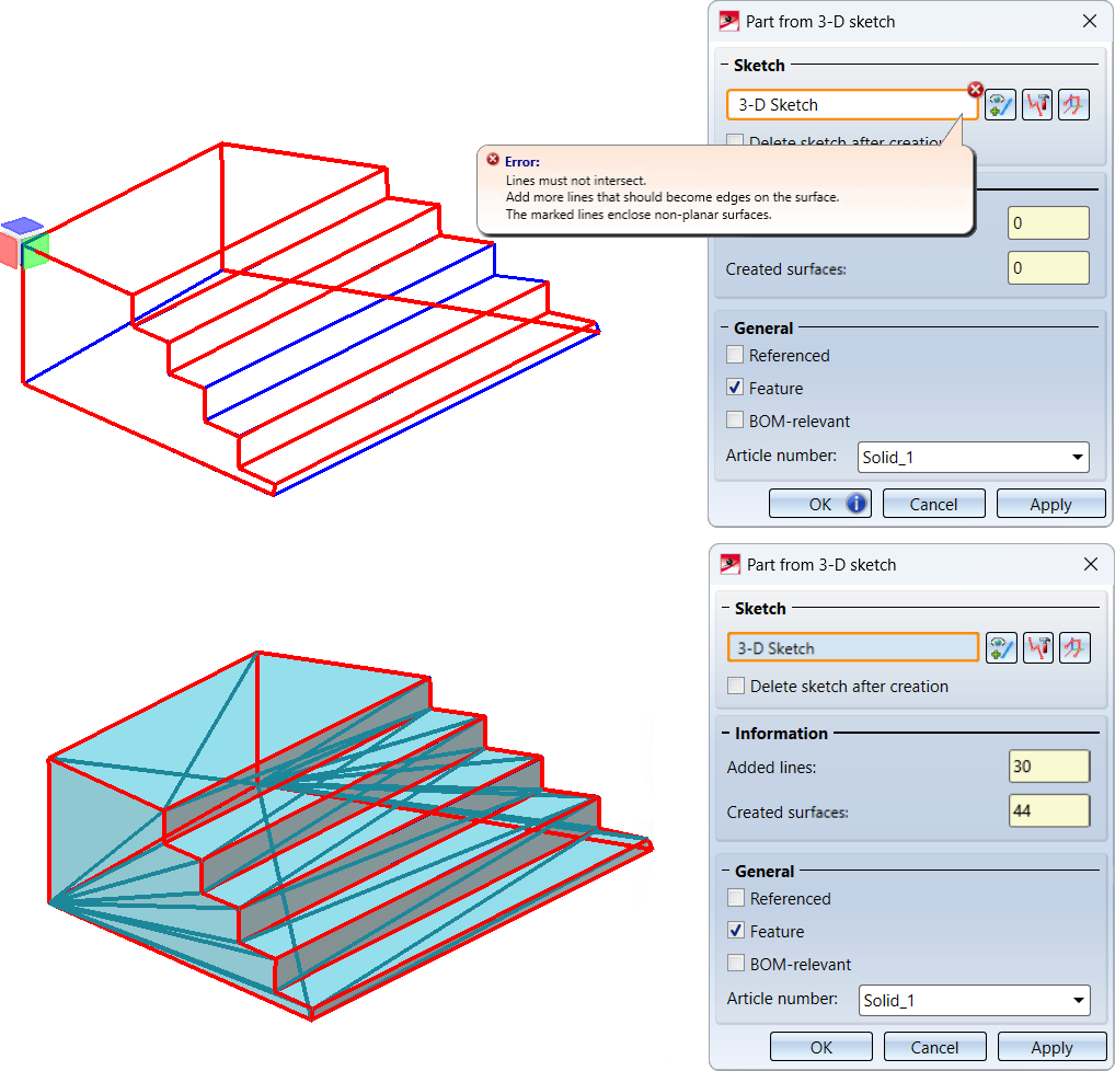
New part from 3-D sketch - optimised algorithm
The algorithm of the New part from 3-D sketch  function has been optimised and now leads to better results and ensures smoother surfaces.
Example:
Let us consider the 3-D sketch shown, which obviously represents a staircase - albeit a somewhat skewed one. Until HiCAD 2023 SP1, it was not possible to convert this sketch into a solid, since the sketch contains lines enclosing non-planar surfaces. As of HiCAD 2023 SP2, this is now possible, since the new algorithm automatically adds the missing lines here.
Extended functionality for processing planes
The Processing plane  function now makes it easier to create processing planes tangential to non-planar, i.e. curved, surfaces. After selecting such a surface, a preview of the processing plane will "hang" on the cursor. The position of the plane can then be explicitly defined by selecting a point, e.g. by selecting a point on an attached part or by using the 3-D point options. The point is projected onto the surface and its projection to the origin of the processing plane. The processing plane is tangential to the selected surface.
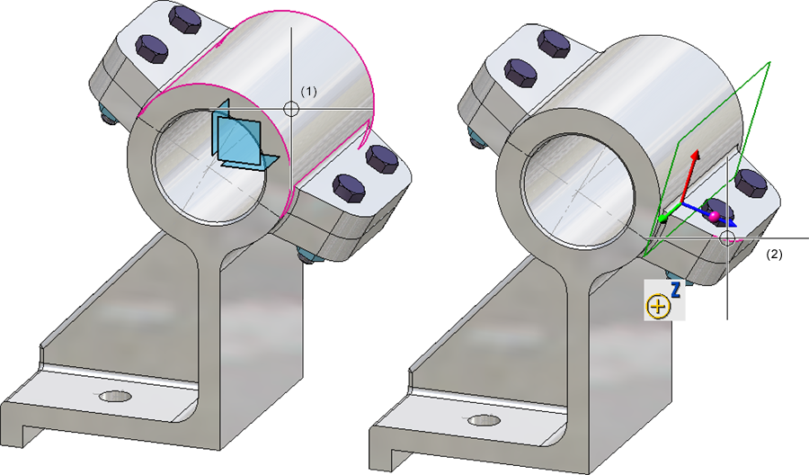
(1) Selected surface, (2) Point in the centre of the rounding
Furthermore, the context menu has been extended.
|
|
Plane perpendicular to screen plane This function creates a plane perpendicular to the screen plane. The Z-direction of the plane is determined by selecting two points or by selecting a line, and depends on the order in which the points are selected or on which line end is closer to the cursor during the selection. |

|
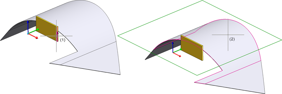
Tangential to surface with direction The function replaces the previous function Tangential to surface, parallel to plane With this function, you can place the processing plane tangentially to a surface. However, the direction must first be selected. This can be done by selecting two points, a straight line, a surface or a processing plane. Once the direction has been determined, select the surface to which the processing plane is to run tangentially. Only analytical surfaces are permitted.
(1) Direction, (2) Selected surface |

Execution of standard processing during the drawing derivation
Standard processings that are inserted using the functions under
|
|
|
|
|


can be assigned a processing ID via the Feature log, which defined where the standard processing is to be performed - on the site or in the workshop. The Type parameter is available for this purpose. During the drawing derivation, no distinction was previously made between the different versions when annotating standard processings. This is possible as of SP2.
If this is desired, the following requirements must be met:
- Different annotation templates for workshop and site must be available as FTD files.
- In the Configuration Editor, under Drawing> Annotations > Annotation template, the checkbox Different annotation for workshop and site must be activated. In the lines below, the annotation templates must be specified including the path. The path can be a HiCAD drive letter or a Windows path.
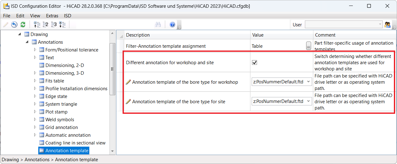
If these requirements are fulfilled, then during the drawing derivation, standard processing operations are annotated differently depending on the processing ID.
Coat 3-D part
In addition to sheet metal parts and beams, the Coating function can now also be used to process general 3-D parts. However, it is not possible to select a different coating for the back side here.
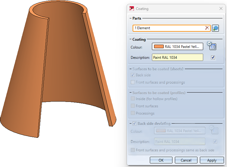
You can find the function under Sheet Metal > Process > Coating.
Service Pack 1 2023 (V 2801)
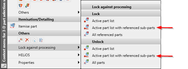
Locking parts with multiple selection
Multiple selection is now also possible when locking or unlocking parts against processing.
Part and dimension orientation
Previously, the functions for determining Part orientation and Dimension orientation were only available in the context menu for 3-D parts. As of SP1, you can also find them on the Drawing tab under Positioning/Detailing > Orient.... At the same time, the function icons have been modernised.
Calculation of dimensions - Sorting the attributes length, width, height
If the automatic calculation of dimensions is active, the dimensions of assemblies and parts are automatically calculated by HiCAD and assigned to the attributes
- Length ($03),
- Width ($02) and
- Height ($04)
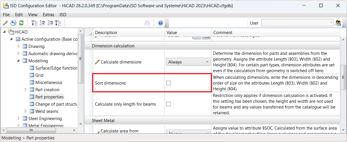
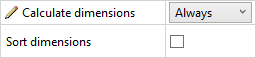
of the part / assembly. As of HiCAD 2023 SP1, it is now possible to assign the dimensions to these attributes sorted by size, i.e. the largest value is assigned to the length, the smallest to the height. To do this, the new checkbox Sort dimensions must be activated in the Configuration Editor under Modelling > Part properties. By default, the checkbox is inactive.
Example:
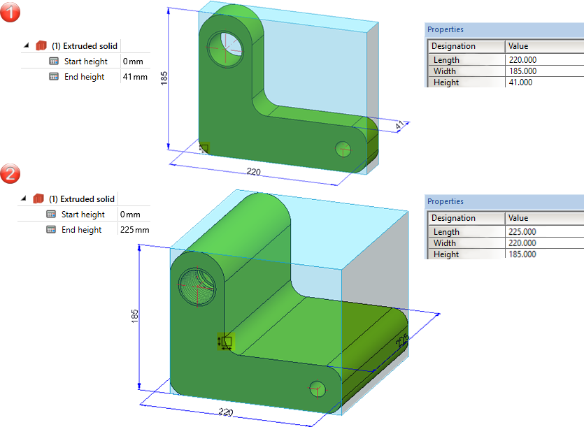
Case 1:
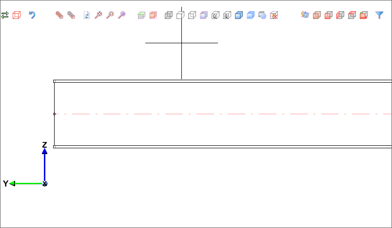
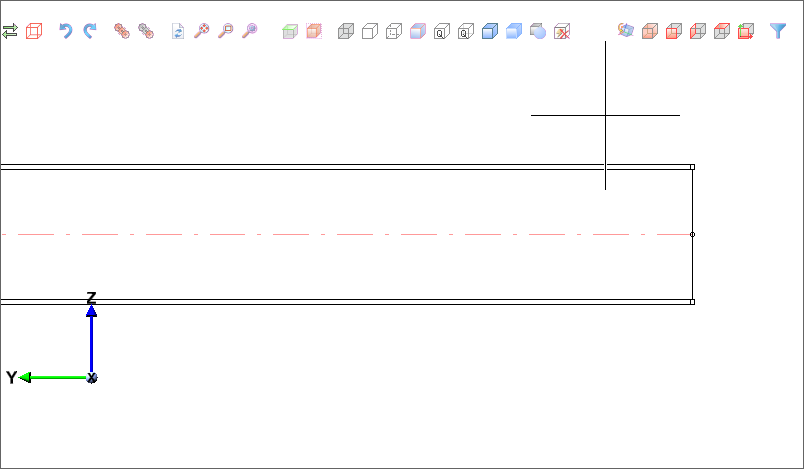
In the following example, the automatic calculation of dimensions is active, but the sorting is inactive. (1) shows the initial situation. Now the height of the extruded solid is changed in the Feature (2). This changes only the Height attribute.
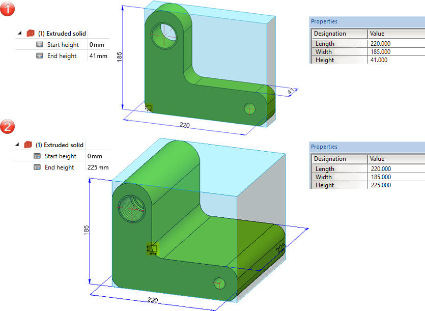
Case 2:
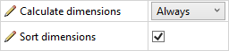
We consider the same example, but now both the automatic calculation of dimensions and the sorting are active. (1) shows the initial situation. Now the height of the extruded solid is changed in the Feature (2). This makes the height the largest value and assigns it to the Length attribute. The length value from step 1 becomes the width, the width value becomes the height. This means that all attribute values change.
Switching on the sorting will only take effect after HiCAD has been restarted.
Itemisation
Transferring the part orientation during the itemisation
Parts with the same item number now have the same part orientation - analogously to the dimension orientation. In detail, the procedure is as follows:
- If a part orientation is manually assigned to a part that has not yet been itemised, this orientation will also be transferred to all existing geometrically identical parts, provided that they have not yet been itemised.
- If parts with manually assigned part orientation are present during the itemisation, it will be transferred to all parts with the same item number.
- If new parts are inserted or changed in the drawing, the system will check whether identical parts with a manually assigned orientation already exist. If so, their orientation will be transferred to the new/changed part, provided that no manual orientation has been assigned to this part. If, on the other hand, the new part has a manually set part orientation, it will be adopted for the already itemised identical part.
Itemise parts according to part filters
In the Itemise part  function, the filters defined for automatic part annotation can now also be used for annotating templates. The dialogue window has been extended accordingly for this purpose.
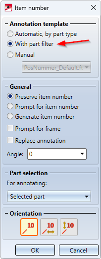
By selecting this option, you can, for example, use different annotation templates for beams and sheets, sheets and plates or different beam types. The filters that can be set in the Configuration Editor correspond to the filters of the part search via the transparent HiCAD toolbar. To learn how to use these filters, refer to the section Using part filters for automatic part annotation and itemisation.
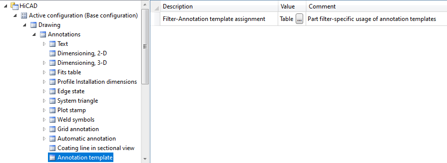
In connection with this extension, the setting of the filters in the Configuration Editor has been moved. As of SP1, you can find the settings under Drawing > Annotations > Annotation template.
Itemise part - Increment range of numbers
The Increment range of numbers  now takes the By top level assemblies itemisation mode into account. This means that if the By top level assemblies itemisation mode is active, only the numbers of the parts that were also itemised in this mode will be increased.
Sketches
Configuration of the graphic display
When working with sketches, especially when drawing sketch elements, various information is displayed in the model drawing, for example, the length of the line, the angle or the radius of the arc.
The colour display and text height of these displays can now be changed in the Configuration Editor, e.g.
You can find the settings at System settings > Identification.
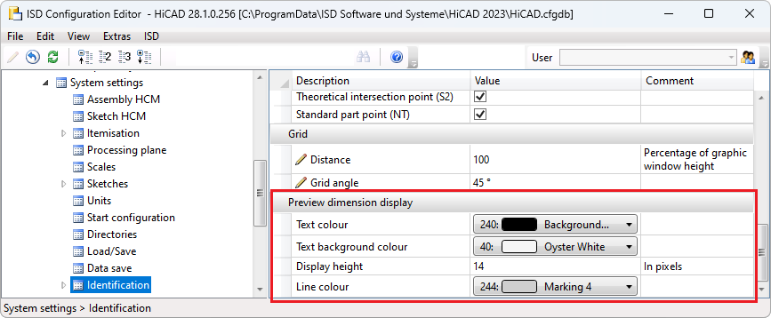
Please note that the settings apply not only to the Sketch Technology, but also to other functions that use this type of text display. For example, the change of the display height is also considered for the Change route function.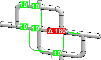
Extension when moving and cloning sketch elements
The functions
have been extended.
- If a straight line, a surface or an axis is selected to determine the displacement, the distance will now be displayed directly in the calculator and not in the dialogue window as before.
- Undo is possible when the dialogue window is open.
- The Cancel button has been removed from the dialogue windows. You now use the middle mouse button to cancel the function.
- The graphical representation of the part coordinate system is hidden during the execution of the function.
Views
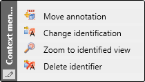
Move annotation
The context menu of view markings has been extended. The Move annotation moves the complete view marking, i.e. symbol and text.
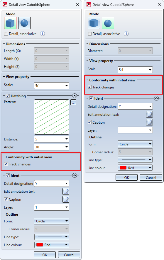
Detail views cuboid/sphere - Conformity with initial view
Analogously to the "normal" detail views, as of SP1 it is now also possible when creating detail views cuboid/sphere to specify whether the detail view should be associative to the initial view or not. For this purpose, the dialogue window has been extended accordingly.
Associativity to the initial view means that the detail view inherits certain changes from the source view. These are:
-
cut-outs (including the creation and deletion of cut-outs),
- the section path (if the initial view is a sectional view) and
-
hatchings of cut and cut-out surfaces.
Moving master views
A master view, i.e. a view that is superordinate to other views, could previously only be moved together with all linked views. In the detailing process, however, it may be necessary to move only the individual view.
As of SP1, this is now possible. For this purpose, the Do not move linked views  function is available in the context menu of the Move view function.
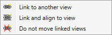
You activate the context menu during dragging (i.e. while the views are hanging on the cursor) by right-clicking.
Update view caption
New in the context menu for view captions is the Update view caption  function. This function allows you to update the position and content of view captions.
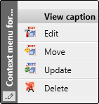
The function is useful for sectional/detail views, for example. Here the captions are normally centred above the view. If annotations are then set or changed, the caption will no longer be centred. It will adjust its position only when the view is updated. Here the function can be used to restore the alignment. Additionally, the content of the caption will be updated if necessary.
Set fixed view point
New in the Required position menu is the function

Use this function to fix the active view at a point associative to the geometry.
You must determine this point with a point option (Autopilot, keyboard or point option menu). Taking over the current cursor position by mouse click is not a point associative to the geometry and therefore not possible as a fixed point.
If a fixed point is already defined for the active view, it will be highlighted in colour in the drawing.
The fixed point is stored by HiCAD in associative form, its projection in 2-D natural coordinates. After changes to the part geometry, the preliminary new projection of the 3-D point is calculated and the view is shifted to that the projection falls back to the previously saved 2-D natural coordinates.
In detail, the following applies:
- If the geometry changes, HiCAD moves the view so that the specified fixed point, which may be in a different location in 3-D, is in the same location in the drawing (2-D). This means that the coordinates of the point in the cartesian XY coordinate system (natural coordinates) do not change.
- If the scale changes, the same applies as for geometry changes. However, this only applies if no fixed point is specified interactively for the scale change.
- If you move the view explicitly, for example manually via Drag&Drop or via the API, the fixed point in the drawing also moves.
- If you rotate the view dynamically around a point (mouse or space mouse), the fixed point in the drawing will shift unless the view is rotated around the fixed point. The fixed point will also shift when you rotate around an axis of the active coordinate system. For all other changes of the projection - even when you rotate around an axis of the world or image coordinate system or when you rotate incrementally - the fixed point will keep its position in the drawing.
.
Example:
Let us consider the beam shown.
If you set the fixed view point to the start point of the beam axis (1) and select the left beam end (2) for the length change (e.g. 500) then the position of the fixed point will be retained.
Without a fixed point, the result would look like this:
The function is also available in the context menu for views.
Major Release 2023 (V 2800)
Calculation of dimensions and orientation
Until now, automatic calculation of dimensions was only possible for assemblies. As of HiCAD 2023, this feature will also be supported for 3-D parts. If the dimensions of assemblies and parts should be calculated automatically and assigned to the attributes
- Length ($03),
- Width ($02) and
- Height ($04)
of the part / assembly, this must be set in the Configuration Editor.
In addition, you can specify whether the dimensions should also be shown in the drawing.
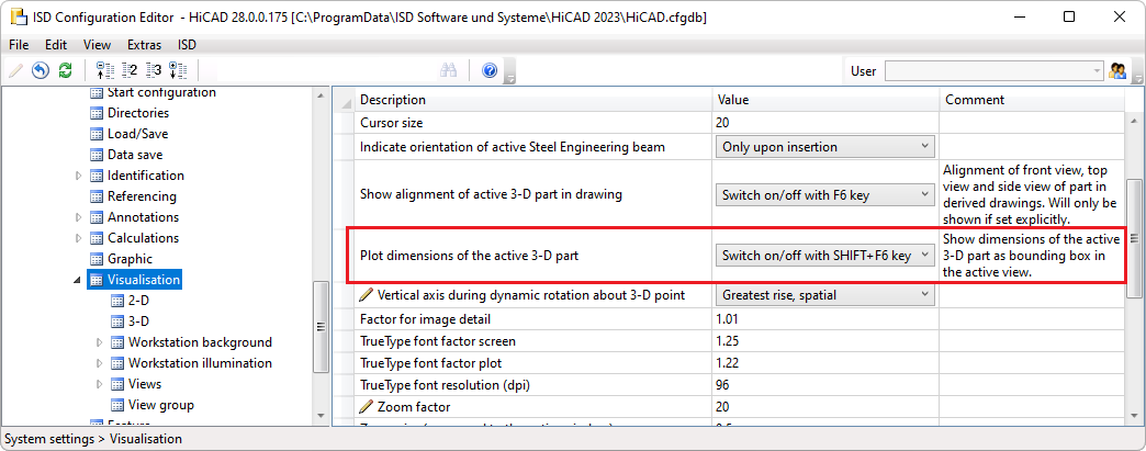
The display is in the form of the so-called bounding box (1). This is the smallest cuboid that completely encloses the part. In addition, the coordinate system (2) is displayed on the bounding box. The coloured arrows of the coordinate system indicate the direction of the dimensions:
- Red: x-axis (length),
- Green: y-axis (width),
- Blue: z-axis (height).
Additionally, the bounding box is marked by a symbol (3) that indicates the up-to-dateness of the dimensions as well as the source of the orientation.
The orientation of the bounding box (dimension orientation) plays a role in the calculation of dimensions, because it determines which values are assigned to the Length, Width and Height attributes. The dimension orientation is determined according to the following priorities:
- The orientation is set manually. As of HiCAD 2023, the corresponding features are available in the context menu for parts and assemblies under Properties > Dimension orientation:
 orientation of the dimension by selecting the front side
 orientation of the dimension by selecting the top side
 Reset dimension orientation (for manually set orientations)
- The orientation results from the part orientation.
- The orientation results from the processing direction.
- The orientation results from the part coordinate system.
The following table contains an overview of the possible markings on the bounding box.
|
Symbol |
Meaning |
|---|---|
|
|
The dimensions are not up-to-date. This occurs, for example, if you have selected the Only for automatic itemization setting under Modelling > Part properties > Calculate dimensions, since in this case the dimensions are only calculated / updated during the itemisation. |
|
|
The dimensions are up-to-date, the dimension orientation corresponds to the part coordinate system. |
|
|
The dimensions are up-to-date, the dimension orientation results from the processing direction. |
|
|
The dimensions are up-to-date, the dimension orientation results from the part orientation. |
|
|
The dimensions are up-to-date. The dimension orientation was set manually. |
|
|
The dimensions are up-to-date, the dimension orientation corresponds to the part coordinate system of the main part of the assembly. |
|
|
The dimensions are up-to-date, the dimension orientation results from the processing direction of the main part of the assembly. |
|
|
The dimensions are up-to-date, the dimension orientation results from the part orientation of the main part of the assembly. |
|
|
The dimensions are up-to-date. The dimension orientation of the main part of the assembly was set manually. |


If parts/assemblies are to be excluded from the calculation of dimensions, this can be specified - as before - by assigning the Ignore for dimensions (#NDR) attribute.
Restrictions on the calculation of dimensions
Not all parts/elements are included in the calculation of dimensions.
| Excluded from the calculation of dimensions | |
|---|---|
|
Parts / Assemblies |
The above-mentioned parts / assemblies are considered in the calculation of dimensions of superordinate parts / assemblies. |
|
Geometrical elements |
These elements are generally not considered. |
|
Parts in assemblies |
These parts are not considered when calculating the dimensions of assemblies. |
Restrictions on the dimension orientation
Changing the dimension orientation is generally not possible for parts that are locked against processing. However, they are considered when calculating the dimensions.
There is also a restriction for steel engineering plates, glasses and beams.
- Steel engineering plates, glasses
The height must point in the direction of the sheet thickness. - Beams
The length must point in the direction of the beam axis, the height corresponds to the web.
Lock parts against processing
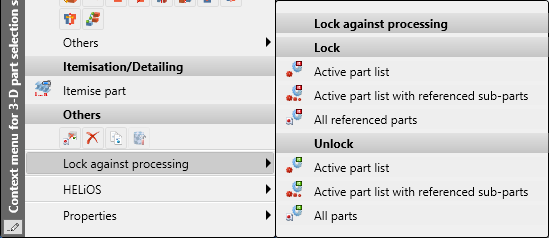
Until now, locking parts against processing was only possible for externally referenced parts. As of HiCAD 2023, this is now also supported for non-referenced and internally referenced parts. Locking against processing can be useful, for example, to protect an adjacent structure from unintentional processing.
This extension means that the functions for locking parts against processing are now available in a separate menu and not in the Referencing functions menu as before. You can access the function via the context menu for parts and there via the entry Lock against processing.
Dimension parameters
Saving the dimension parameters with the drawing
As of HiCAD 2023, the current settings of the Set parameters for new dimensions  function are saved together with the drawing, i.e. in the corresponding SZA file, when a drawing is saved. When the drawing is loaded again, these parameters will then automatically be active.
After starting HiCAD, when creating a new drawing and when loading drawings saved with a version prior to HiCAD 2023, the parameter values set in the Configuration Editor under Drawing > Annotations > Dimensioning, 3-D will be active.
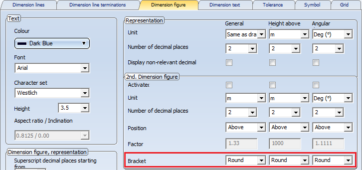
Selecting the bracket type for the 2nd unit of measurement
The 2nd unit of measurement was previously marked with round brackets. As of HiCAD 2023, the bracket type can now be selected:
- Round brackets,
- Square bracket or
- Without brackets.
You can change the setting on the Dimension figure tab of the dialogues for the units of measurement. This applies to general dimensions as well as to parameter and HCM dimensions.
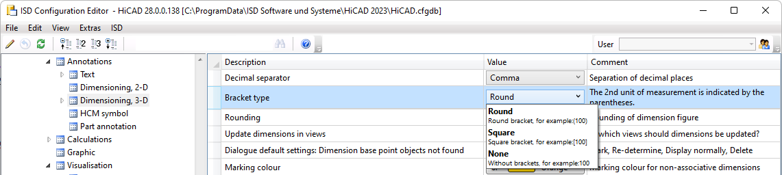
The preset can be defined in the Configuration Editor under System settings > Annotations > Dimensioning, 3-D.
Edge state - Dimension unit
The dimension unit selected in the Configuration Editor under Drawing > Annotations > Edge state is used to display the edge state. It can be selected independently of the dimension unit of the drawing.
Example:
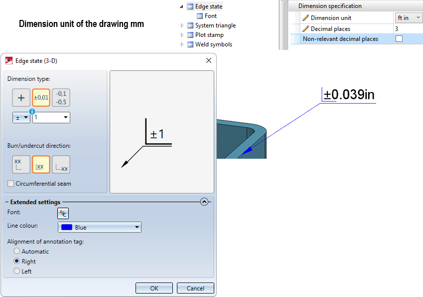
The dimension unit selected for the edge state in the Configuration Editor applies to subsequently created annotations. Annotations that already exist in a drawing and that were created with different settings will not be automatically converted. When editing these annotations, the corresponding values will be marked in the dialogue.
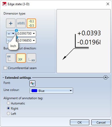
The dimension unit is not output if millimetres "mm" is selected for both the unit of length of the drawing and the dimension unit of the edge state.
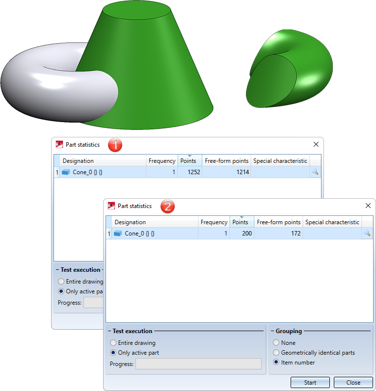
Improved surface cuts between torus and cone/cylinder/torus
The algorithm for surface cuts between toruses and cones, cylinders or further toruses has been revised. This results in significantly fewer free-form points, which leads to improved performance and better quality results.
In the image, the intersection of the cone and the torus has been created. (1) shows the number of free-form points before HiCAD 2023, (2) shows the number in HiCAD 2023.
3-D grid
The dialogue window of the 3-D grid function has been modernised.
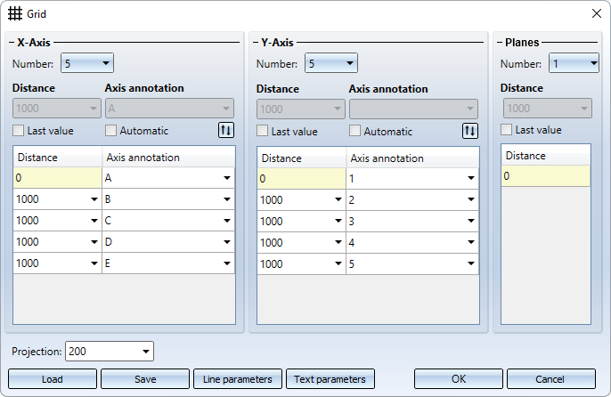
Another new feature is that you can use formulas instead of values when specifying the distance - even in mixed units. The value will then be converted to the unit of measurement of the drawing.
Example:
Unit of measurement of the drawing: mm; Distance: 1 3/4" + 12.5 mm  Result: 56.95 (mm)
Sketches
Sketch technology - Presets distance/angle grid
The value for the angle grid when drawing planar sketches and 3-D sketches can now be preset in the Configuration Editor under System settings > Identification in the Grid area.
In this context, the preset for the distance grid has also been moved to this area.
Please note that the specified grid settings not only apply to the sketch technology, but also to other functions that use distance and angle grids. One example is the new insertion function for beams.
Transform sketch - Move line elements and points
The functions

have been revised and optimised. The distance of the displacement is now no longer specified in the dialogue window, but can be set dynamically on a distance grid in X and Y direction. In addition, you have the option to freely select the displacement direction via a context menu.
![]()
Clone sketch - Clone, copy line elements
The function icon of the Clone GE, Move function has changed  .
.
New is the function
This function creates a copy of line elements/isolated points of a sketch that can be placed multiple times at different locations.
Referenced parts and itemisation
If an already existing referenced part is inserted in a drawing that is an itemised source model, the item number of the part (if present) will be invalidated and thus be shown crossed out (or marked with *). When subsequently itemised, the part receives a change marker  in the ICN. This also applies to all its identical parts. Thus, further updates of the referenced part and its item number are always guaranteed.
If the current drawing is not an itemised source model, the item number of the part will be loaded/updated according to the corresponding KRA file.
Background cut-outs for annotations
In the case of background cut-outs of annotations, the interruption area was always rectangular up to now. As of HiCAD 2023, the frame selected in the annotation settings is taken into account. This means that circular interruption areas are also possible, for example.
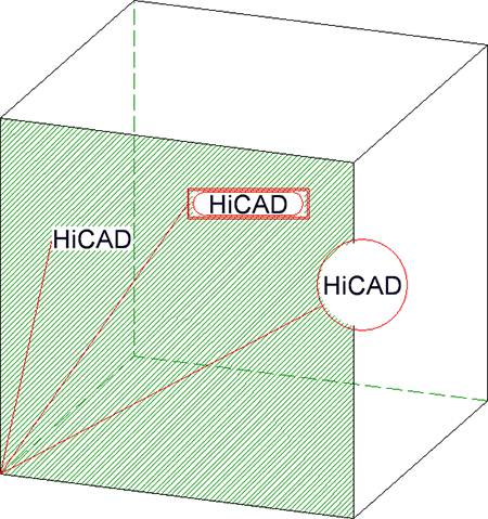
- Background cut-outs are possible for all annotation functions. After HiCAD has been started, the setting defined in the Configuration Editor under System settings > Annotations > Part annotation > Interrupt background lines will be used for new annotations. The ISD default setting is
 Exclude background. If this setting is changed during the current HiCAD session when a new annotation is created, this will apply as the new default setting for subsequently created annotations.
 - For annotations from drawings created with HiCAD 2022, the setting from the Configuration Editor is used when drawing or editing for the first time. Annotations from versions prior to HiCAD 2022 must be converted for this purpose. Whether and when the conversion should take place can be defined in the Configuration Editor under Compatibility> Annotations > Part annotation, 3-D.
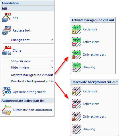
- Background cut-outs can also be set or removed in one step for multiple annotations. Corresponding functions are available under 3-D Dimensioning + Text > Text > Part annotation, with free text and leader line > Activate background cut-out or 3-D Dimensioning + Text > Text > Part annotation, with free text and leader line > Deactivate background cut-out.
Associative detail views
As of HiCAD 2023, when creating detail views, you can specify whether the detail view should be associative to the initial view or not. For this purpose, the New detail view and Change detail view dialogue windows have been extended accordingly.
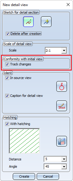
Associativity to the initial view means that the detail view inherits certain changes from the initial view. These are:
- cut-outs (including the creation and deletion of cut-outs),
- the section path (if the initial view is a sectional view) and
- hatchings of cut and cut-out surfaces.
Please note the following instructions if the checkbox is active (ISD default setting).
- Associativity must be set when defining the detail view. It cannot be set subsequently.
- Cut-outs and section paths that are inherited, i.e. originate from the initial view, cannot be edited in an associative detail view. This is only possible in the initial view. However, the detail view can also have its own cut-outs, which can then of course also be edited in the view.
- An associative detail view cannot change its initial view. Marking the detail outline is possible only in this specific initial view.
- When deleting the initial view, the associativity of the detail view is lost. However, the detail view itself does not change.
- The associativity of a detail view can be removed with the Change detail view function. This does not change the detail view, it just no longer follows the changes of its initial view. Cut-outs ans section paths originally "inherited" from the initial view become the detail view's "own" cut-outs and section paths.
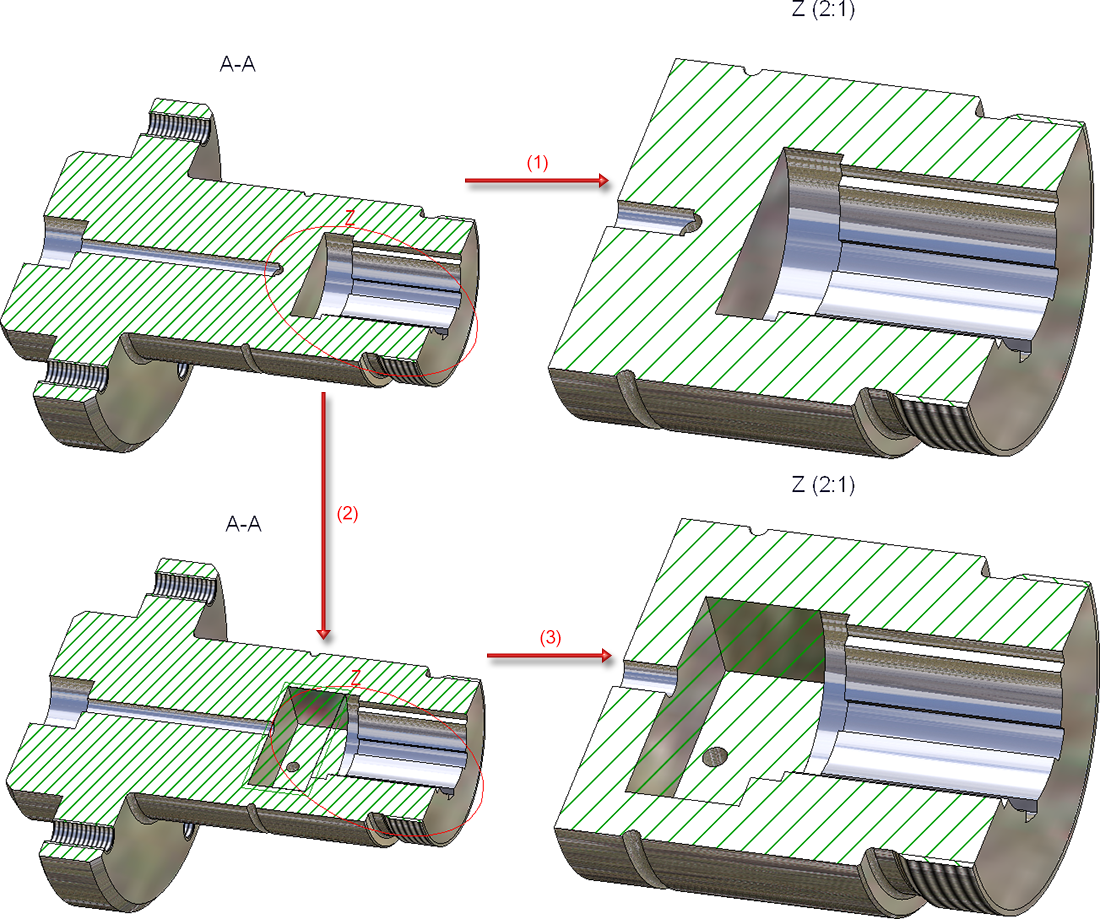
Example:
The figure shows a section view A-A with an associative detail view Z derived from it (1). Subsequently, a cut-out has been inserted into the sectional view (2). This cut-out is then transferred to the detail view after updating (3).
Existing detail views from older drawings (before HiCAD 2023) are non-associative and cannot be set to associative.
