Sheet Metal > Sheet development > Export >  > Export sheet developments
With this function you can export several developments with different parameter settings, e.g. for LVD and Bystronic, from one or several Sheet Metal parts.
You can choose between the following formats:
- DXF/DWG,
- XML for CADMAN-B (from Version 7.5) by LVD and
- GEO for (ToPs GEO)
When you call the function the following dialogue will be displayed:
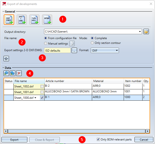
1. Output file
3. Parameters for STEP and ToPS GEO
4. Data

Output file
In this area you choose the file format for the export.
|
|
If you click on this icon, you choose the export of a development as DXF or DWG file (AutoCAD). In the DXF settings you can choose between DXF and DWG. You can either export a complete development or a section contour. |
|
|
If you click on this icon, you can export the sheet developments from HiCAD as XML file for CADMAN-B (from Version 7.5 onwards) by LVD. Also, an additional DXF file will be created. A prerequisite for the output of LVD data is the assigning of bending tools to the bend zone with the Bend zone tooling |
|
|
The ToPs GEO icon allows a direct export of the development from HiCAD to the GEO file format. The GEO data can be directly loaded into the individual modules (Laser etc.) of the ToPs family. |
|
|
The STEP format allows a standardized data exchange between two different CAD systems. STEP is primarily used for transferring the geometry data of solid models. In this way, time-consuming manual rework of transferred data can be avoided. |


 function.

General parameters
|
Output directory |
Here you enter the directory for the export files. Click on the folder icon |
|
File name |
Clicking on the The annotation settings can also be saved as Favourites. The file format is *.FTD. In the HiCAD SYS directory you will find the pre-configured file SheetToDXF.FTD. You load the file by activating the option From configuration file. |
|
Mode |
Here you specify for DXF/DWG files whether only the section contours (the drawn bend zones and angles will not be considered) or the complete developments are to be exported. |
|
DXF settings |
For the DXF export you can determine via the settings, e.g.:
You can load the ISD defaults with this icon |
|
Format |
If you have chosen DXF/DWG as output file, you can specify the file extension here. |
|
|
The settings of the dialogue window can be saved as Favourites and reused at any time. To do this, click on the More on favourites management can be found in the Manage Favourites topic of the HiCAD Basics Help. |
 to choose an existing folder on your computer or to create a new one.
  icon while the
  , customise them with the
Parameters
STEP
If you choose the STEP format instead, you have the following options:
|
Transfer layers |
The layer on which the edge is located (e.g. bend lines on Layer 2) will be transferred during export. |
|
Transfer colours |
The colour will be transferred during export. If you have deactivated this option, you cannot use the Export fits information via surface colour option (see below). |
|
Export fits information via surface colour |
By activating or deactivating this checkbox you can determine whether fits information are to be exported by means of a surface colour. For this to happen, the Transfer colours checkbox (see above) needs to be deactivated. The diameter of the corresponding bore will then be highlighted in a different colour in the imported STEP part. In the SYS directory of your HiCAD installation you find the configuration file FITINFO_COLOR.DAT, in which it is determined which RGB value are to be assigned to which fits information. |
|
Export free points |
By activating or deactivating this checkbox you can determine whether the exporting of free points in the model drawing should be allowed or suppressed (if they could cause problems in other places). |
|
Export free edges |
By activating or deactivating this checkbox you can determine whether the export of free edges in the model drawing should be allowed or suppressed (if they could cause problems in other places). |
|
Thread body |
Choose As separate parts or United with parent part if you want thread bodies to be exported as individual parts or united with their superordinate part, respectively, in the model drawing. Choose Do not transfer if you do not want the thread bodies to be exported. |
ToPS GEO
When outputting ToPsGEO data, the assignment from the file CAMIntHICAD_GEO.ini will be evaluated. By activating the Export forming edges option, you determine whether moulding tools and cross-breaks are to be taken into account during export.
Data
|
|
Use this icon to select the sheets for export in the drawing. |
|
|
This icon shows all sheets contained in the drawing in the export list. |
|
|
Use this icon to delete selected sheets from the export list. |
|
|
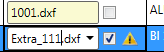
If the part attributes set in the Editor cannot be applied to the sheets, you have the option to enter your own file name. To do this, activate the checkbox and enter the file name. |
|
Only BOM-relevant parts |
If you have activated this checkbox, only developments the sheets of which consider the BOM-relevance among the part attributes will appear in the export list. |


Apply/discard value inputs
|
Export |
When you click on the Export button, temporary developments will be generated and output of all sheets in the export list, according to the specified parameters. The status icon |
|
Close & Report |
The Close & Report button activates the Report Manager and creates a BOM. If you did not itemize the Sheet Metal part in HiCAD, quantities will be set on 0 here. All attributes will be transferred to the Report Manager (as with drawing creation) and, additionally, the file name and the file path of the export. You can configure a RM SETTINGS file with the Report Manager, determining which data are to be written. You can output these data in a CSV file.
|
|
Close |
Click this button to end the function. |
 will indicate problems that may occur. The files will then be located in the specified directory.
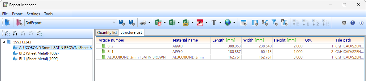
![]() Please note:
Please note:
If a countersunk bore is located at the edge of the sheet and HiCAD generates the development, it will always choose the smaller radius for the development. For chamfers the longer side will be selected.
The text in the development will not be exported if you have deactivated the text with the Show/Hide, via element type function (Drawing > Visual. > ...).
