"Civil Engineering" docking window" > Steel Engineering > Stairs+Railings > Stairs > Staircase Configurator
Use the new Staircase Generator to create single-flight, straight stringer staircases with intermediate platforms - with or without utilisation of stairwell contours. Individual settings, such as various stringer or step variants, as well as various connection options for stairs to stringers, or the definition of standardized platforms are available.
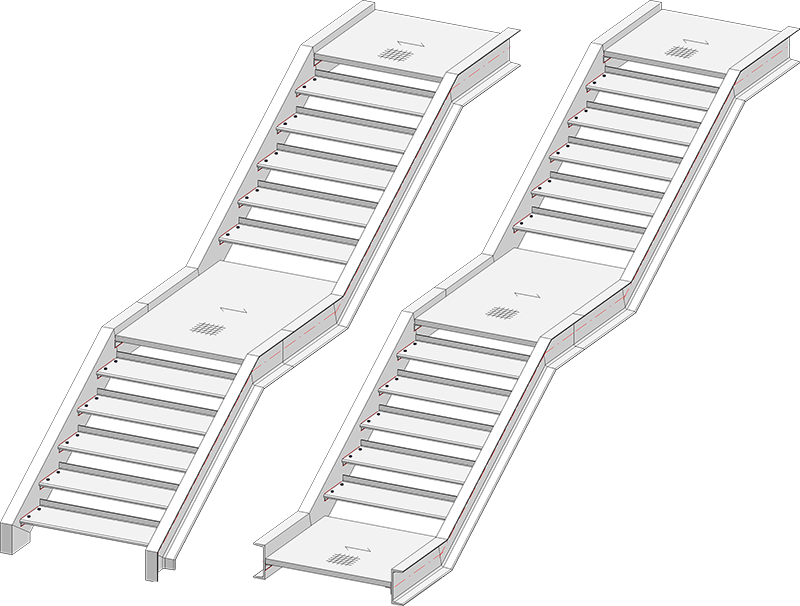
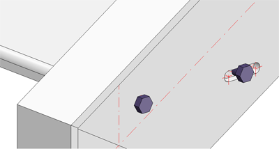
Left: Staircase with entrance stringer as pillar, intermediate and landing platform; Right: Staircase with entrance, intermediate and landing platform
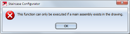
A prerequisite for the start of the Staircase Configurator is that the current drawing contains a main assembly. If this is not the case, a corresponding message will be displayed.
Extensive information on main assemblies can be found in the topics
Assemblies, Main Parts and Sub-Parts,
Part Drawing or Assembly Drawing and
Edit Part/Assembly Structure .
After calling the Staircase Configurator, HiCAD will prompt you to identify the stairwell, or to press the middle mouse button if you want to work without stairwell.
Working with stairwell contours
Here you fit the staircase into a stairwell. For this to happen, a suitable sketch for the stairwell must exist in your drawing. This sketch serves the purpose of positioning the staircase in the stairwell and defining the stair start (the so-called "entrance"). Therefore, the first step will be creation of a stairwell with the help, of the functions on the Sketch tab.
The length of the stairwell must not be smaller than the total length of the staircase. If this is the case, HiCAD will display an error message.
Identify the sketch in the vicinity of the stair start.
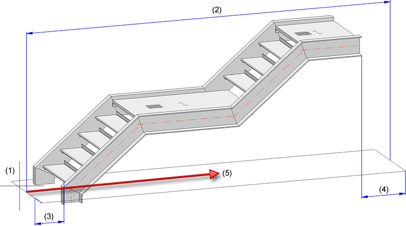
(1) Identified sketch, (2) Sketch length, (3) Distance at stair start, (4) Distance at stair end, (5) Walking direction
If you work without a stairwell contour, the fitting point of the staircase will be placed in the origin of the World Coordinate System. You can freely select this fitting point when you insert the staircase.
The input fields of the Staircase Configurator dialogue window will always be initialised with the last saved values when you open it to create a new staircase.
The window consists of the following tabs:
- Calculation
Size of the staircase, number of steps and platforms. - Stringers
Configuration of the stringers. - Platforms
Configuration of the platforms and the mounting to the stringers and stairs. - Steps
Configuration of the steps and their mounting to the stringers. - Mounting/Bolt assignment
Insertion of assembly joints.
Specify the desired staircase parameters on the tabs.
Click OK to start the staircase generation.
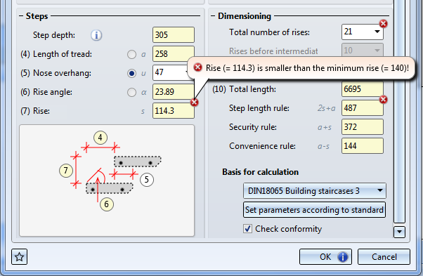
If the Check conformity checkbox has been activated, HiCAD will first check whether the staircase can actually be constructed on the basis of the specified parameters. If this is not the case, the  symbol will be shown on the OK button. In the dialogue window, fields with an incorrect value will be marked with the
  symbol. Move the cursor over the symbol to obtain further information, and correct the staircase parameter. You can click on the Set parameters according to standard button to correct the parameters automatically.
If the check was successful, HiCAD starts with the staircase generation. The current status of the generation will be indicated by a progress bar at the bottom of the window. A feature called Stairway will be entered in the Feature log.
Working with Favourites
The settings specified in the dialogue window can be saved as favourites and re-used at any time if desired. To do this, click the  symbol at the bottom left of the dialogue window.
More information on favourites management can be found in the Manage Favourites topic of the HiCAD Basics Help.

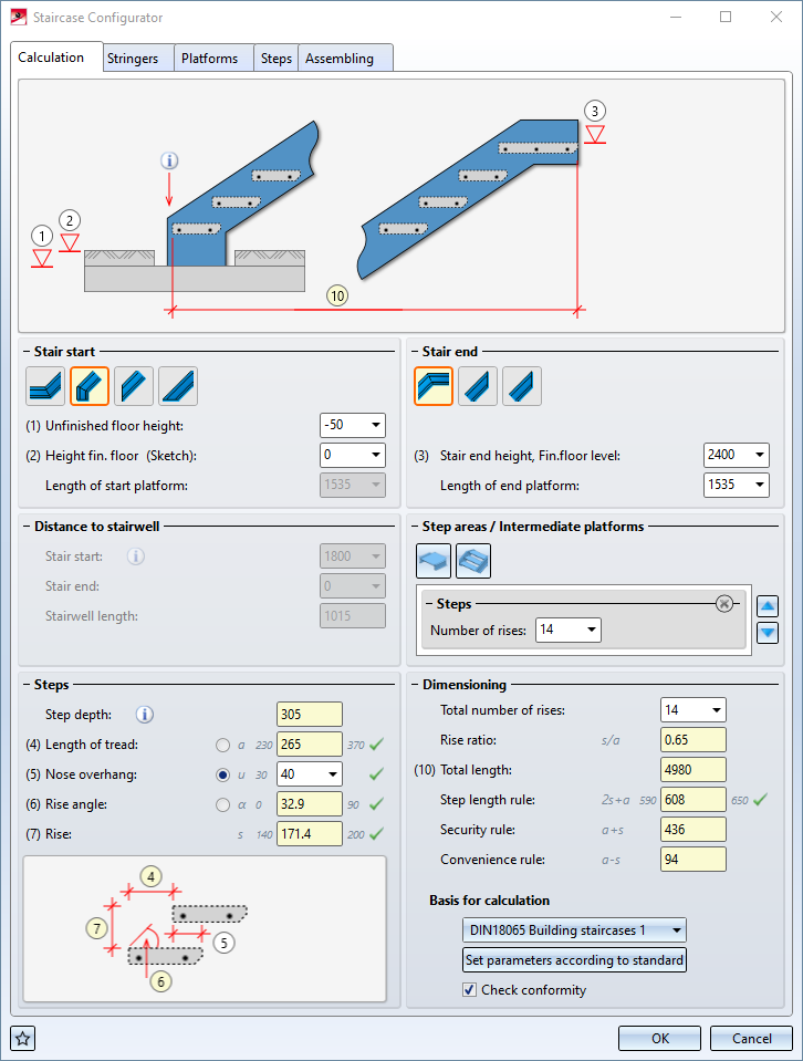
'Calculation' tab
On this tab you specify the size of the staircase, the number of steps and platforms.

Stair start
Here you choose the type of the stair start by clicking on the corresponding symbol. The graphic in the dialogue window will then be automatically adjusted accordingly.
|
Type |
Parameters |
|
|---|---|---|
|
|
Stair start with platform |
|
|
|
Entrance stringer as pillar |
|
|
|
Cut, vertically |
|
|
|
Cut, horizontally |
|


Depending on the stair start type you then specify the height of the finished floor and the platform length. If a flooring will be used, which requires the taking into account of an "unfinished floor", enter this value here, too.
If you choose "Entrance stringer with pillar", the height of the pillar will be automatically calculated automatically, based on the value for the unfinished floor.
Stair end
Here you choose the type of the stair end by clicking on the corresponding symbol. The graphic in the dialogue window will then be automatically adjusted accordingly.
|
Type |
Parameters |
|
|---|---|---|
|
|
Stair end with platform |
|
|
|
Cut, rear edge last step |
|
|
|
Cut, perpendicular, stair end |
|


Distance to stairwell
When you work with a stairwell contour, you can specify the stair start and the stair end (distance of stair start and stair end to stairwell), as well as the stairwell length here. When you work without a stairwell contour, these fields will be greyed out.
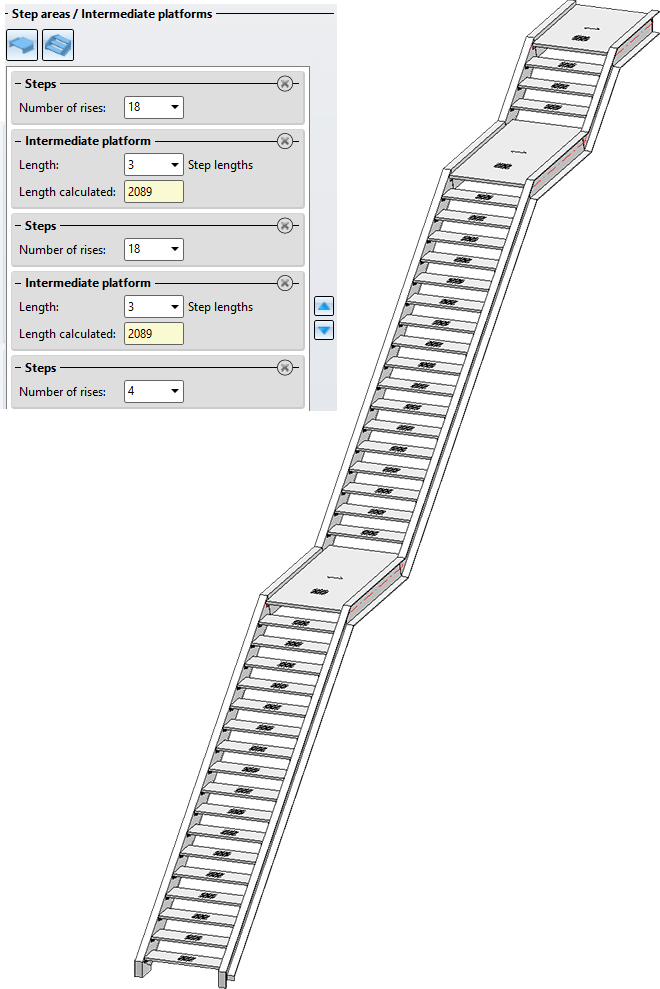
Step areas / Intermediate platforms
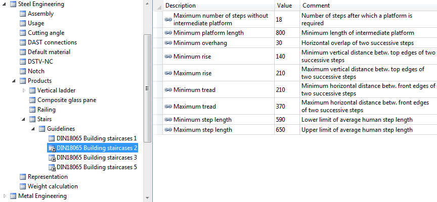
In addition to platforms at the stair start and stair end, several intermediate platforms are now possible. It should be noted that intermediate platforms must be added depending on the DIN standard. For example, according to DIN 18065, a maximum of 18 steps without intermediate platforms is possible for building staircases. This means that the staircase may have to be divided into several staircase segments, whereby an intermediate platform must be installed between two staircase segments.
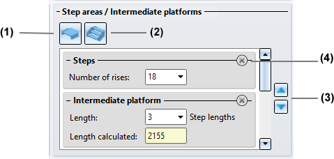
(1) Click on  to insert an intermediate platform. Enter the length of the platform in step lengths. Note that the last element in this area must be a stair segment and that several platforms must not follow each other.
(2) Click on  to insert a stair segment (steps). Enter the number of rises. Note that there must always be a platform between two stair segments.
(3) Click on the delete symbol to remove a stair segment or an intermediate platform.
(4) Use the arrow symbols to change the order of the stair segments and intermediate platforms.
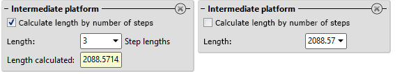
You can specify for intermediate platforms whether the length of the platform is to be calculated by the number of steps or by entering a value. The checkbox Calculate length by number of steps is available for this purpose. If the checkbox is active (default setting), the length is automatically calculated and displayed after entering the number of steps. This value cannot be edited. If the checkbox is not active, you can determine the length by entering a value.
Steps
The parameters for the steps are as follows:
- the Length of tread a
- the Nose overhang u
This is the horizontal dimension by which the front edge of a step projects, seen from the top view, "into" the depth of the step beneath it. - the Rise angle α
For a good accessibility of a staircase a value between 30° and 45° is recommended. - the Rise s
This is the height from step to step. this value is calculated automatically.
You can enter one of the parameters a, u and α here. To be able to do this you need to activate the radio button next the the input field. The other values and the Rise s will then be calculated on the basis of the entered value and the values entered for Total number of rises and Rise before intermediate platform in the Dimensioning area of the dialogue window.
The step depth results from the step variant chosen on the Steps tab of the dialogue window.
Dimensioning / Basis for calculation
Here you can specify the Total number of rises and Rise before intermediate platform.
The other values will be automatically calculated by HiCAD on the basis of the specified parameters:
- Rise ratio s/a,
- Total length of the staircase,
- Step length rule 2s+a (for a good accessibility of a staircase a value of 630 is recommended.)
- Security rule a+s (tread + rise)
- Convenience rule a-s (tread - rise)
Basis for calculation
In the listbox you can choose the guideline to be respected for the calculation. These guidelines, e.g. national regulations for stair construction, are specified in the Configuration Editor at Steel Engineering > Products > Staircase > Guidelines. The regulations according to DIN 18065 have ben pre-set here. For defining further guidelines, right-click on one of the existing guidelines and choose Derive structure in the context menu.
If the Check conformity checkbox has been activated, HiCAD will first check whether the staircase can actually be constructed on the basis of the specified parameters. If this is not the case, the symbol will be shown on the OK button. In the dialogue window, fields with an incorrect value will be marked with the symbol. Move the cursor over the symbol to obtain further information, and correct the staircase parameter. You can click on the Set parameters according to standard button to correct the parameters automatically.
To place the cursor in a particular input field, you can also click on the corresponding markers in the graphic of the dialogue window. If, for example, you click on the marker in the graphic of the Calculation tab, the cursor will be placed in the Unfinished floor input field.
'Stringers' tab
On this tab you can specify the stringers to be used for the staircase.
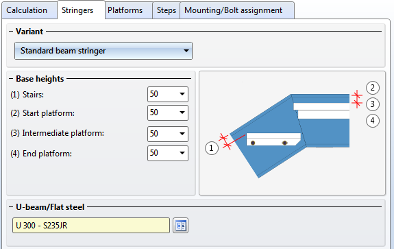
First select the variant:
- Standard beam stringer,
- Sheet Metal U stringer,
- Sheet Metal C stringer, or
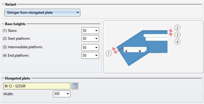
- Stringer from elongated plate.
Then, enter the base offsets for platforms and stairs.
Select - depending on the selected stringer variant - the beam or the plate/sheet from the HiCAD catalogue by clicking the  symbol. In the case of Sheet Metal stringers you need to specify the parameters Width, top (1), Width, bottom (2) and Height (3).
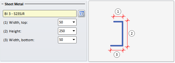
If you use Sheet Metal U stringers, specify the desired values for Width, top (1), Height (2) and Width, bottom (3).
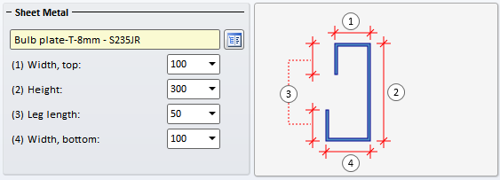
If you use Sheet Metal C stringers, specify the desired values for Width, top (1), Height (2), Leg length (3) and Width, bottom (4).
For elongated plates you determine the width of the stringer:
'Platforms' tab
Here you specify the data for the entrance, landing and intermediate platform.
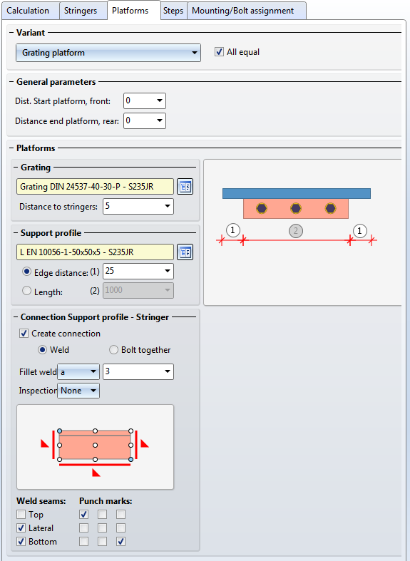
Specify the distance of the entrance platform at the front, and the landing platform at the rear. If you want to use the same data for different platforms, activate the All equal checkbox.
Grating
Currently only grating platforms are available. Click the symbol and select the desired grating from the catalogue. Enter a distance to the stringers.
Support profile
Select the support profile from the catalogue by clicking the symbol, and specify its size - either by entering the edge distance or the length.
Connection Support profile - Stringer
Activate this checkbox if you want to create a connection between support profile and stringer. You can choose between a bolted and a welded connection.
- Bolt together
Activate the checkbox and select the desired bolting. Proceed as you would do for Steel Engineering Bolting function. For an easier assembling you can also use slots: Activate the Slot checkbox and enter the slot width. Then, specify the horizontal distance between two bolts. The vertical distance (distance of bolt from upper edge of support profile) can be entered directly, or automatically calculated, taking the tracing dimensions into account. The Tracing dimension checkbox is activated by default. - Weld
Specify the fillet weld thickness and the inspection category. Also, specify which weld seams and punch marks are to be created by activating or deactivating the corresponding checkboxes.
Connection Grating - Support profile
If desired, proceed likewise to specify the bolted connection between grating and support profile .
'Steps' tab
Here you specify the data for the stair steps.
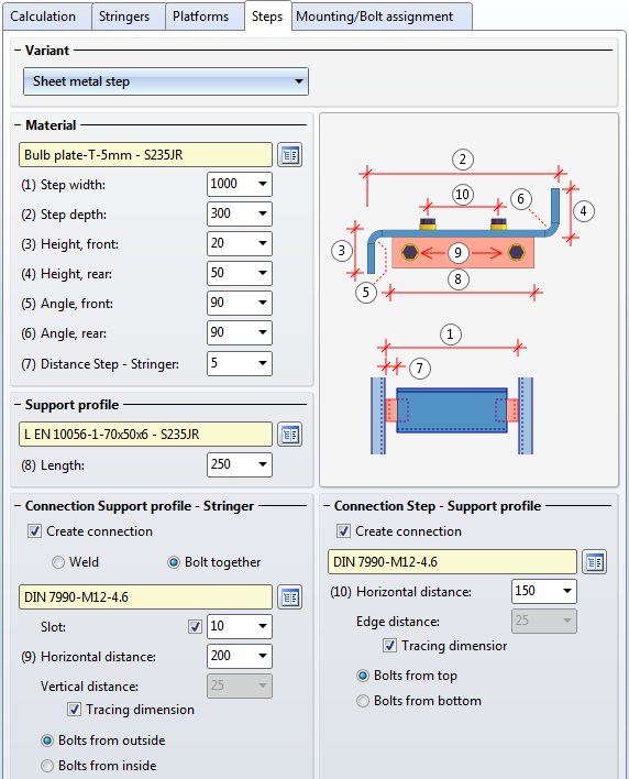
Variants/Material
Select the desired variant and enter the required data.
- Standardized grating step
Select the desired grating step from the catalogue and specify the width and depth of the grating step. If you want to mount the gratings by means of boltings, activate the With bolting checkbox. - Free grating step
In contrast to the standardized grating step, the distance between step and stringer, the type and the length of the support profile, the connection between step and support profile, and the connection between support profile and stringer are freely configurable. - Sheet Metal step
Select the desired sheet metal part from the catalogue. Specify the following parameters: Step depth, Height front/rear, Angle front/rear, Step width, Distance Step-Stringer. - Sheet Metal step w/o support profile
In contrast to the normal Sheet Metal step, the step will have a lateral flange enabling a mounting to the stringer by means of bolts.
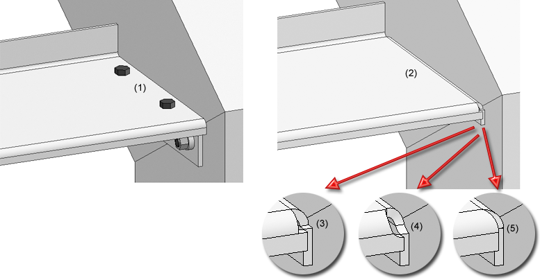
(1) Sheet Metal step, (2) Sheet Metal step without support profile - Corner processing: Rectangular cut-out (3), Circular cut-out (4), Closed (5)
- Wooden step
Select the desired wood from the catalogue. Specify the width and depth of the step and the distance between step and stringer.
Support profile
Select the support profile from the catalogue and specify its length.
Connection, Stringer
If you want to create a connection between support profile and stringer, activate the corresponding checkbox. You can choose between a bolted or a welded connection. Please note however that bolted connections are only possible for particular support profiles, e.g.for L-beams.
- Bolt together
Activate the checkbox and select the desired bolting. Proceed as you would do for Steel Engineering Bolting function. For an easier assembling you can also use slots: Activate the Slot checkbox and enter the slot width. Then, specify the horizontal distance between two bolts. The vertical distance (distance of bolt from upper edge of support profile) can be entered directly, or automatically calculated, taking the tracing dimensions into account. The Tracing dimension checkbox is activated by default.
- Weld
Specify the fillet weld thickness and the inspection category. Also, specify which weld seams and punch marks are to be created by activating or deactivating the corresponding checkboxes.
Connection, Step
If desired, proceed likewise to specify the bolted connection to the step.
'Assembling' tab
On this tab you specify whether (and which) assembly joints between staircase sections are to be created.
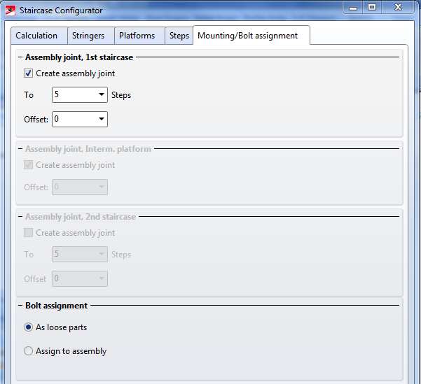
One distinguishes between:
- Assembly joint, 1st staircase
Specify after how many steps the assembly joint is to be created. - Assembly joint, intermediate platform
Enter an offset from the centre of the intermediate platform in walking direction. - Assembly joint, 1st staircase
Specify after how many steps the assembly joint is to be created.
Boltings can be installed as loose parts or be assigned to the assembly of the respective level. Activate the desired option. When installing them as loose parts the bolting connections will be assigned to the Accessory Parts assembly.

Staircase Configurator - Important Notes (3-D SE) • Stairs and Railings (3-D SE) • Sketch (3-D)