Working with Sketches

Planar sketches and 3-D sketches
Sketches are 3-D parts with free lines/edges lying in a plane. They are, for instance, used
- for deriving of extruded parts, bores and exclusions and
- for C-edge sweeps and for sectional views.
A 3-D Sketch is a combination of graphical elements, i.e. of lines and circles, without any surface references. 3-D sketches can, for instance, be used
- for generation of surfaces,
- for defining of consecutive points or point meshes for free-form geometries, or
- as guidelines during placing of cross-sections. In the process, the points of a 3-D sketch will be interpreted as support points of a curve.
The following applies for both planar sketches and 3-D sketches:
- Both have the geometry type Part with free edges, but differ with regard to the part type.
- Sketches have no Feature log, and not Feature log can be inserted.
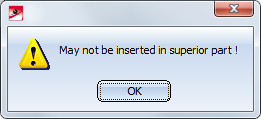
- Sketches cannot have any sub-parts. If you attempt to assign a sub-part to them, the following message will be displayed:
An overview of sketches:
|
|
Planar sketch |
3-D sketch |
|---|---|---|
|
Part type |
Sketch |
3-D sketch |
|
Geometry type |
Part with free edges |
Part with free edges |
|
Symbol in ICN |
|
|
|
Feature possible? |
No |
No |
|
Sub-parts possible? |
No |
No |


 Since planar sketches and 3-D sketches are different part types, Part filters can be applied separately for planar sketches and 3-D sketcheswhen using the Find
  function.
The functions for the creation and processing of sketches can be found on the Sketch tab. This tab is activated automatically when you choose a planar sketch or a 3-D sketch in the drawing or in the ICN.
Purpose and representation of sketches
HiCAD assigns a purpose to both planar sketches and 3-D sketches upon their creation. This purpose influences, among other things, the representation of sketches. HiCAD distinguishes between
- Purpose: Create/Edit and
- Purpose: Part.
Sketches with the purpose Create/Edit are in principle "auxiliary elements" from which other parts or processings, or sectional views, detail views or cut-outs can be derived. Sketches with this purpose are represented in the active by broader lines, and they are also visible in the shaded model.
Sketches with the purpose Part are interpreted by HiCAD as "normal" parts which can be used as elements of a model drawing. The differ from sketches with the purpose Create/Edit as follows:
- In sectional views, detail views and cut-outs, the sketch will be cut.
- A special representation is not available, and in the shaded mode (without edges) the sketch will not be represented.
- The sketch can be processed, like a normal part, with the functions at 3-D-Standard > Tools > Crossh., i.e. it may contain centre lines, crosshairs etc.
Which purpose will be automatically assigned can be specified in the Configuration Editor at System settings > Sketches. Also, you can specify here how sketches that are created or used in conjunction with other functions, e.g. during the definition of sectional or detail views, or the creation of extruded or revolved parts.
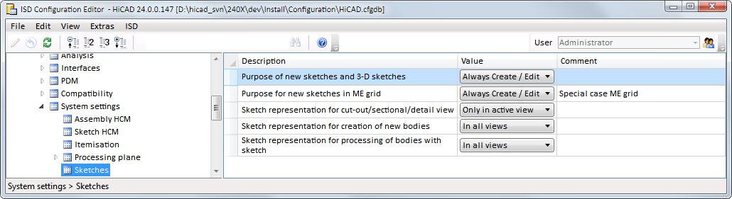
- Purpose of new sketches and 3-D sketches
Here you determine which purpose is to be assigned to a new sketch: - Always Create/Edit
This is the default setting. - Always part
- Always query
Always asks you to specify the purpose whenever you create a new sketch.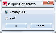
- Purpose for new sketches in ME grid
This setting is for sketches that have been created via the Metal Construction plugin. Here, the Always query is not available. - Sketch representation for cut-out/sectional/detail view
This setting concerns sketches that are created during defining of sectional views, detail views and cut-outs. These sketches can be represented in all views or only in the active view (default). - Sketch representation for creation of new bodies
This setting concerns sketches that were created for the generation of new bodies, e.g. by means of the functions Extrtruded solid, Revolved solid, C-edge sweep, Sheet from sketch etc. These sketches can be represented in all views (default) or only in the active view. - Sketch representation for processing of bodies with sketch
This setting concerns sketches that were created during the processing of bodies, e.g. by means of the functions Subtract, Add, etc. These sketches can be represented in all views (default) or only in the active view.
To change the purpose of a sketch, choose Sketch > Tools > Sort GE  > Change purpose
 . You can also access this function in the context menu of the sketch via Properties.
Sketch HCM
- Both sketches and 3-D sketches can be parameterized with the HCM Constraint Manager, a tool that allows you to position, fix and move elements of sketches. For this to happen, the corresponding geometry elements will be linked to each other by so-called "constraints", i.e. by dimensional conditions, logical connections and restrictions. The parametric logic will transform the affected elements in such a way that the defined constraints will be respected.
- When sketching polylines, circles, arcs and ellipses, the corresponding HCM constraints can also be generated automatically. The individual elements of the polyline are then automatically linked to each other by corresponding dimensional and positional constraints. You can activate the automatism directly when drawing the sketch elements, e.g.:
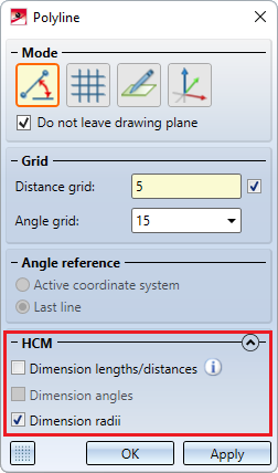
The automatic constraints always refer to the part coordinate system.
While drawing sketch entities, the automatism can also be switched off for individual elements by simultaneously holding down the SHIFT key.
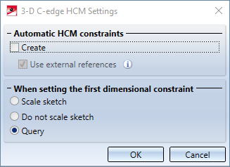
If the automatic setting of HCM constraints is to be switched off in principle, then you must deactivate the Create checkbox in the HCM settings at Sketch > HCM > Tools.
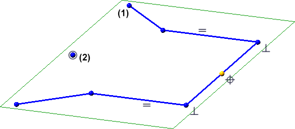
- If the automatism is active or if a sketch is parameterised manually, then the sketch points are highlighted in colour - start and end points of the sketch lines by a filled circle (1), isolated points of the sketch by a filled circle with a ring (2).
The size and colour of the highlighting can be set in the Configuration Editor at System settings > Sketch HCM.
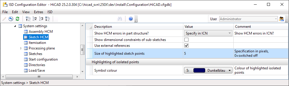
If you do not want to highlight sketch points, set the Size of highlighted sketch points parameter to 0.
- If a part contains sub-parts with HCM constraints, the dimensional constraints can be automatically displayed when you identify the superordinate part. For this to happen, open the Configuration Editor, go to System settings > Sketch HCM and activate the Show dimensional constraints in sub-sketches checkbox.
- If HCM constraints have been assigned to a Sketch, the corresponding dimension or constraint will be automatically marked in the HCM window of the ICN when you click on a dimension text or constraint text. This applies also in reverse.
- 3-D sketches with HCM constraints are marked in the iCN with a lock symbol
 .
. -
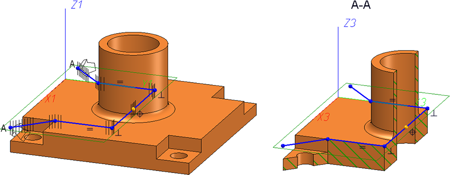
If a parameterized sketch with the purpose Create/Edit is active in a sectional view, the line end points, isolated points and the degrees of freedom of the sketch are also visualized there.
Notes on the point options of the Autopilot
When drawing
- lines and polylines,
- rectangles and parallelograms,
-
circles and ellipses and
- circular arcs and elliptical arcs,
the point options are displayed on the autopilot - depending on the cursor setting and situation - which are highlighted in colour in the Autopilot settings toolbar at the bottom of the HiCAD user interface, e.g.:
In addition, the following restrictions must be observed depending on the situation:
Planar sketches
|
|
T |
F |
O |
S2 |
|---|---|---|---|---|
|
|
|
|
|
|
|
|
|
|
|
|
|
|
|
|
|
 -
-
3-D sketches
|
|
T |
F |
O |
S2 |
|---|---|---|---|---|
|
|
|
|
|
|
|
|
|
|
|
|
|
|
|
|
|
Direction/Axis
When choosing a direction/axis over two points, T, F, O and S2 are offered at the second point, but not at the first point. This affects the following Sketch functions:
- Sketch > Draw > Freehand
> Transition curve - Sketch > Draw > Freehand
- Sketch > Derive > Take O... > Directed
- Sketch > Transform > Move
- Sketch > Transform > Rotate
- Sketch > Transform > Rotate > Move+Rotate
- Sketch > Transform > Mirror
- Sketch > Transform > Scale
- Sketch > Clone > Move
- Sketch > Clone > Rotate
- Sketch > Clone > Rotate > Move+Rotate
- Sketch > Clone > Mirror
- Sketch > Clone > Scale
C-edge HCM
Here S and S2 are offered for all functions, except for dragging.
When using the point option O with regard to the automatic assignment of HCM conditions for circles and arcs, note the following:
- The point option O is also available in the case of a tangential line also being selectable instead of a point.
-
If the point option O is set to determine the centre of a circle or arc or the start point of an arc, then the coincidence constraint is set on the underlying line. If the point is on either the circle or the arc, no coincidence constraint will be set.
Example:
In the illustrated example, an arc is drawn using the Arc  function. For the centre, start and end points of the arc, the point option O is used.
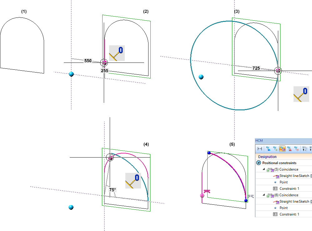
(1) Original sketch, (2) Arc centre point, (3) Arc start point, (4) Arc end point, (5) Outcome with coincidence constraints
Display of the grid reference when sketching
The display of the grid reference when creating sketches and 3-D sketches with the Sketching Tool can be set in the Configuration Editor at System settings > Sketches and there in the section Display of the grid reference.
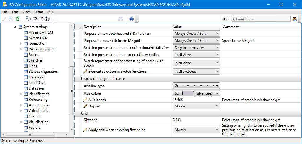
The image shows the ISD default settings.
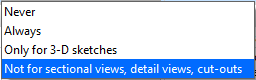
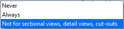
You can set the line type and colour of the axes and the axis length. At Display you can choose when the grid reference should be displayed:
The grid of the first point and the fineness of the distance grid can also be set. The setting for the distance will take effect when HiCAD is restarted.
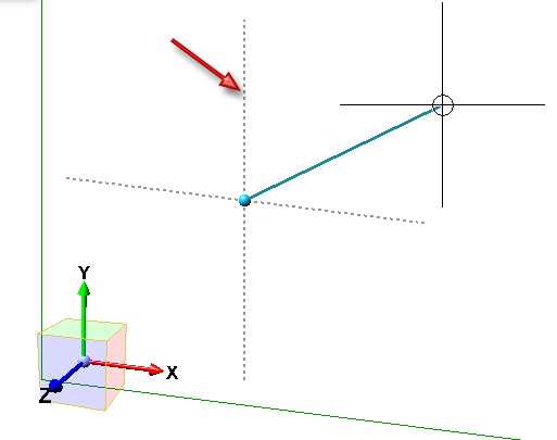
The following settings are possible for the first point:
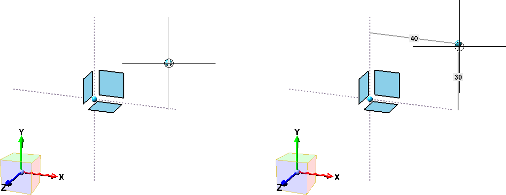
First point, without (left) and with (right) grid display
Others
- When you right-click on a sketch, the context menu for sketches (planar or 3-D sketch) will be opened. Here you can find functions that enable you derive other 3-D parts from a planar sketch, such as extruded solids, revolved solids, beams and profiles, sheets and plates, gratings, glass panes etc. If a sketch is a sub-part to a 3-D solid, the context menu will also provide the Add and Subtract functions.
- The sketch functions offer the option to apply the perpendicular from the current cursor position to the nearest line/edge as a point by holding down the CTRL key and the LMB. Please note that the point option that may be shown at the cursor (e.g. I - End point or M - Mid point) or the sketching grid will be ignored in this case! In other words: It is always the nearest on-line point that will be applied, and not the end point or the displayed grid point.
- If you clone a sketch, the clone will have the same purpose than the original.
