Representation of Profiles
Profile Installation > View Tools > Exact representation 
Profile Installation > View Tools > Contour, cut 
Profile Installation > View Tools > Contour, uncut 
Profile Installation > View Tools > Contour, combined 
Three different representation modes are available for profile installations: Exact representation, Contour, cut, Contour, uncut and Contour, combined. You find these options in the View Tools function group of the Profile Installation Ribbon.
A changing of the representation mode will only affect the active view.
Exact representation
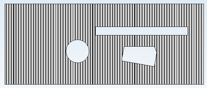
When you choose this representation mode, the profiles will be shown with all their details and processings. This mode is, of course, also the most time intensive. If you work with very many or very large profile installations, it therefore often makes sense to switch to the simpler representation modes.
Contour, cut
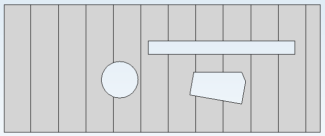
In this representation mode, the profiles are simplified, that is, they are shown as simple cuboids with the correct dimensions and also the complete processings if there are any.
Contour, uncut
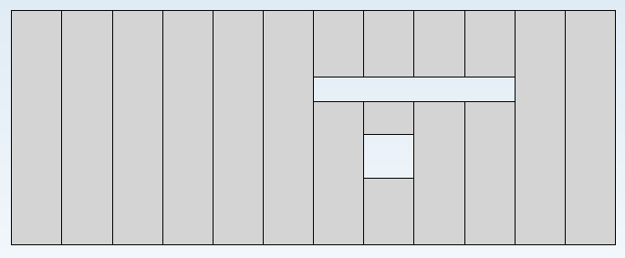
Like in the Contour, cut mode, the profiles are shown simplified here, with the difference that no processings on the profiles are shown here. In the example image, for instance, the round window is not shown, since it does not cut through any profile, but is only cut, as a processing, into the edge of two profiles.
This view is very suitable for a working with the Length optimisation function.
Please note that inserts are shown here only if the setting Split profiles by windows on the Other properties tab has been activated. Otherwise, the inserts will generally be interpreted as processings and will therefore not be shown.
![]() Please note:
Please note:
- In addition to the representation modes described here you have the option to toggle between an exact and simplified representation of the profiles if the utilized profiles contain both views.
- When using the HiddenLine representation it can happen that some profiles will not be shown. In this case, choose a different view mode to show all parts again.

Show profile designations
Profile Installation > View Tools > Add designations 
Profile Installation > View Tools > Delete designations 
It is possible to display profile groups in your drawing according to the usual industry standards. Here, all groups of profiles of the same length that lie next to each other and are contained in the same package are treated as a group. This group is highlighted with a diagonal line and marked with the item number, the number and the length of the profiles.
To do this, select a part of the profile installation in the drawing and then call the function View Tools > Add designations on the Profile Installation ribbon. The layer to which the selected part belongs is viewed and the annotations are added to the drawing.
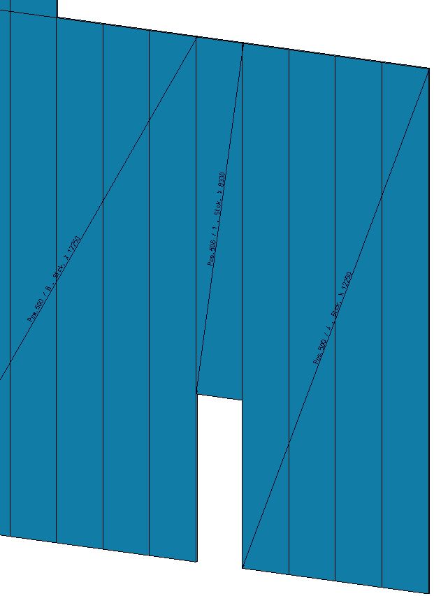
Later you can remove these annotations with the function Delete designations.

Profile Installation • Adding Own Profiles • Other Properties