Sheet Metal - What's New?

Service Pack 2 2022 (V 2702)
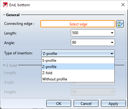
Design Variant - SZ20 Base point with projection
When using ALUCOBOND SZ 20 tray panels, a flange can now be attached at the bottom connection to which an S- or Z-profile or a Z-fold can be automatically riveted.
This use case cannot be realized directly via the Element Installation dialogue window! Instead, a new design variant, SZ20 Base point with projection is available in the Sheet Metal sub-folder of the Civil Engineering functions docking window. The length and angle of the flange can be configured and there are various types of insertion to select from.
Flanges Along Sketch On Surface
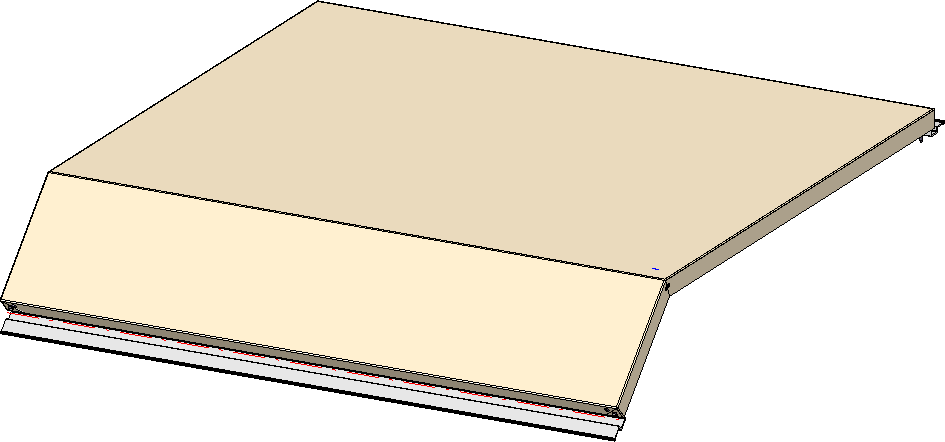
The Flanges Along Sketch On Surface  function has been newly developed and replaces the previous function. With this function you can attach several flanges around a surface in one step. The flanges are derived from a planar sketch and are chamfered taking into account the current Technology parameters.
- A preview of the flanges is displayed, which is immediately updated each time the entries are changed.
- Both edges and surfaces can be selected to determine the surface.
- Parameters such as angle, bend zone or fitting mode can be defined individually for each attachment.
- The function supports the milling edge technique.
- Corner processing / mitre can be defined for adjacent flanges.
- Instead of multiple individual features, the new function creates just one feature, which can be used to change the flanges at any time - in a single step.
In the example displayed, the base surface of a sheet has been selected. The parameters for the attachment on the left edge were selected individually.
Workshop drawing - Sheet metal part as assembly main part
Previously, the drawing derivation did not support the automatic generation of workshop drawings for assemblies if the assembly main part was a sheet metal part. As of SP2, this is now possible - but only if the assembly main part is a cassette-shaped or profile-shaped sheet metal part. The procedure for these assemblies is thus analogous to assemblies in Steel Engineering, which have a profile as the assembly main part. (see also Basics - What's new?)
Service Pack 1 2022 (V 2701)
Attach flanges to surface
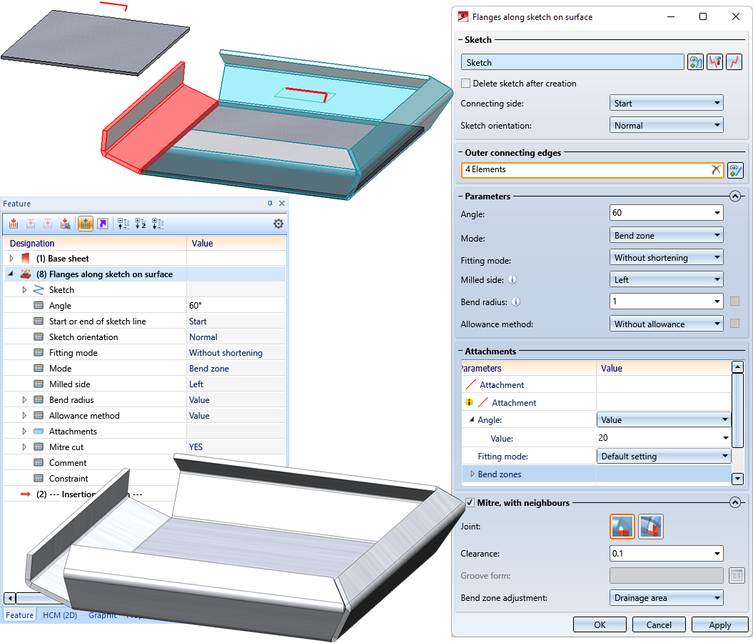
A completely revised version of the function Attach flanges to surface is now available for attaching flanges to a surface. The new dialogue allows you to enter different parameters for each attachment. Furthermore, you have the possibility to define the corner processing directly in the dialogue. You can conveniently change the flanges in one step at any time using the corresponding feature entry.
The choice of the first connecting edge determines the surface and thus also the direction of the flanges. If you select a surface instead of individual connecting edges, all outer edges are taken over for the attachment. To delete individual edges, click on the attachment in the model drawing. It will then be removed from the list.
After selecting the outer connecting edge, a preview of the new flanges is displayed, provided you have not activated any options that require further specifications.
In the Parameters area, you make the default settings for the attachments. Also in this function you have the option to select milling edge zones instead of cylindrical bend zones for composite sheets. Change the parameters for each new flange in the Attachments area by selecting a Value instead of Default setting. Right-click to delete the attachment from the list.
The variant selected in the Process corner area is combined with the joint. Depending on the combination, the input of Clearance, Projection or Diameter is requested.
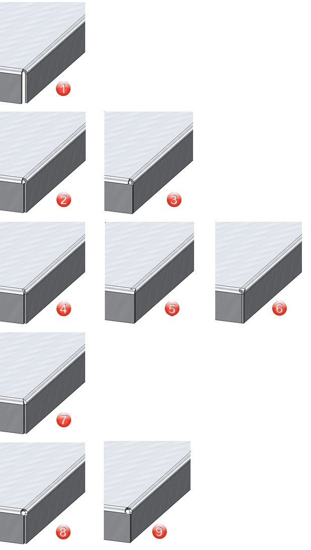
(1) Off (no processing); (2) Close corner, free / Inner edge flush; (3) Close corner,free / Proportional projection; (4) Close corner, closed / Inner edge flush; (5) Close corner, closed / Proportional projection; (6) Close corner, closed / Outer edge flush; (7) Drainage area; (8) Close corner, round / Inner edge flush, (9) Close corner, round / Proportional projection
Example:
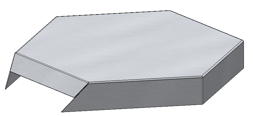
Flanges to surface, with drainage area and clearance; flanges with different angles and lengths
Clean up intersections
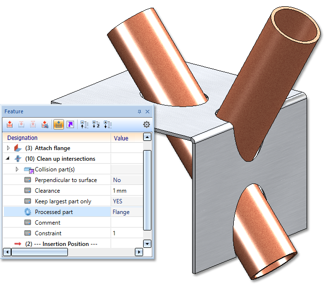
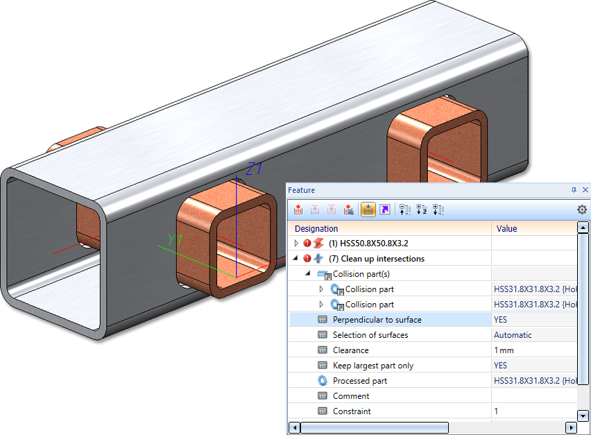
The Clean up intersections function has been completely revised. In contrast to the clean up function in versions before HiCAD 2021 SP1, the new function always processes the whole sheet metal part, not only certain flanges or bend zones. This way a consistent operation is achieved. If it is necessary not to carry out certain clean-ups in a part, you can exclude e.g. flanges or bend zones by selecting individual surfaces in the dialogue.
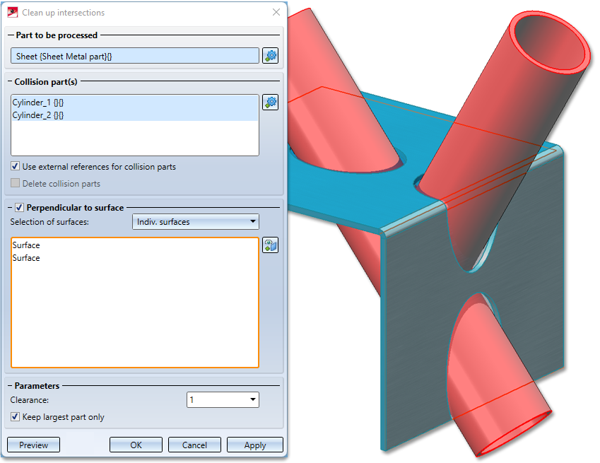
With the option Use external references for collision parts, changes to the collision part will be tracked in the future. That is, if you change the radius of an intersecting cylinder, then after a recalculation of the Clean up intersection feature, the subtractions will be adjusted.
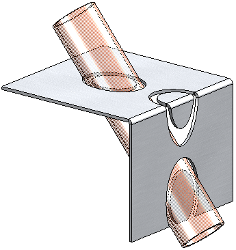
The intersection does not have to be perpendicular to the surface, it can certainly be done for lasers that cut at an angle.
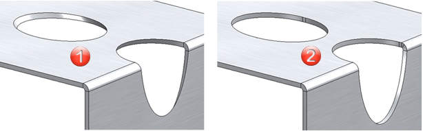
(1) Intersection parallel to the collision parts
(2) Perpendicular to surface
By default, only the largest portion of the intersected part is kept after the clean up. In case you want to keep the small parts as well, the option can be deactivated.
Option Keep largest part only deactivated
Examples:
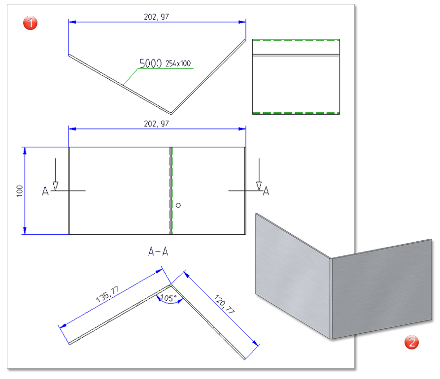
Adjusted sheet corner with stiffener
For the Design variant Sheet corner with stiffener, the flange with the stiffener will now be adjusted in case of different flange lengths.
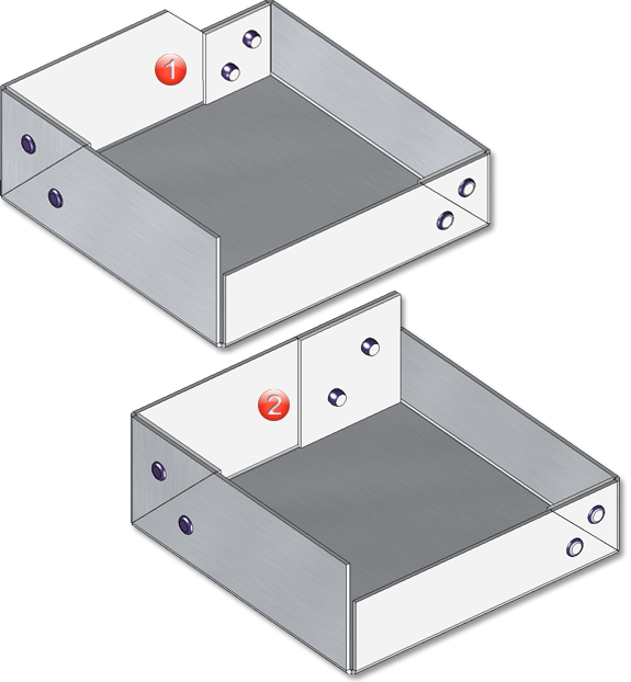
(1) Sheet corner with stiffener in HiCAD 2022 SP1
(2) Sheet corner with stiffener before HiCAD 2022 SP1
Extensions for export via Spooler
The output via the Spooler has been extended by the format ToPs GEO (*.geo). The ToPs GEO export only exports sheet developments or developments of sheets that are available in the drawing.
Section paths of sheet metal parts in derived drawings
The generation of the section path during the automatic drawing derivation of sheet metal parts has been optimised in HiCAD 2022 SP1.
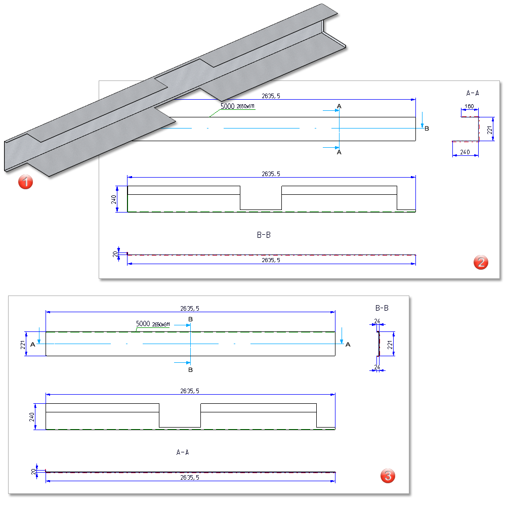
Example of the position of the section path with regard to the processing of outer edges
(1) Sheet metal part
(2) Automatic drawing derivation with sectional views from HiCAD 2022 SP1
(3) Automatic drawing derivation with sectional views before HiCAD 2022 SP1
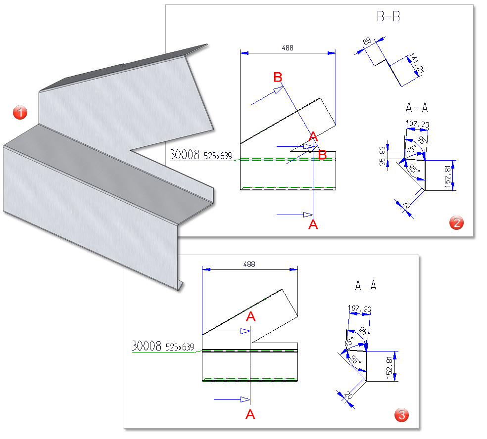
Example with extended sectional views (B - B)
(1) Sheet metal part
(2) Automatic drawing derivation with sectional views as of HiCAD 2022 SP1
(3) Automatic drawing derivation with sectional views before HiCAD 2022 SP1
(1) In this example the sectional view is now generated
(2) Sheet metal part
Feature icons adapted
For some functions, there were previously differences between the icons in the feature and in the menu bar. The icons seen on the menu bar are now also used in the feature log.
Sub-parts of sheet metal parts
With HiCAD 2021, the possibility to itemise parts that are sub-parts of a sheet metal part in the part structure has been abolished. However, this has proved to be problematic in some customer drawings. Therefore, this behaviour has been reversed reversed in HiCAD 2022 SP1.
This means that parts that are sub-parts of a sheet metal part will now be itemised again (if they are BOM-relevant). However, this does not apply to flanges and bend zones, which are not itemised.
Major Release 2022 (V 2700)
New function: Merge flanges/bend zones
The new Merge flanges/bend zones  function has been developed mainly to assist you in joining different Sheet Metal parts. For example, you can join two Sheet Metal parts with the Connect sheets
  function and then merge the adjacent flanges or bend zones. The prerequisite is that the elements lie on one plane and touch each other.
After selecting the function, the dialogue for collecting the flanges or bend zones appears. Identify the flanges to be united by clicking near the adjacent edges. After a right-click you can select the flanges or bend zones in the ICN or in the drawing one after the other. Multiple selection is also possible. If you want to remove a pair from the list, activate it with the right mouse button and then select Remove element(s) from list  .
.
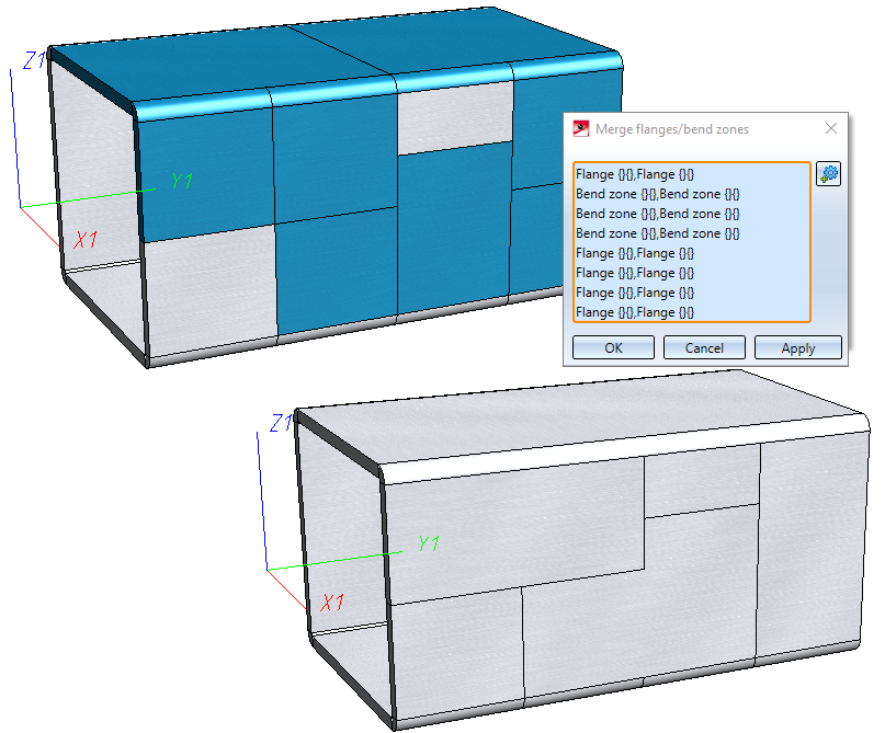
When merging the pairs, the system first checks whether they can be united, otherwise an error message appears. As the list is processed one after the other, flanges (or bend zones) can be united several times with different flanges in one step.
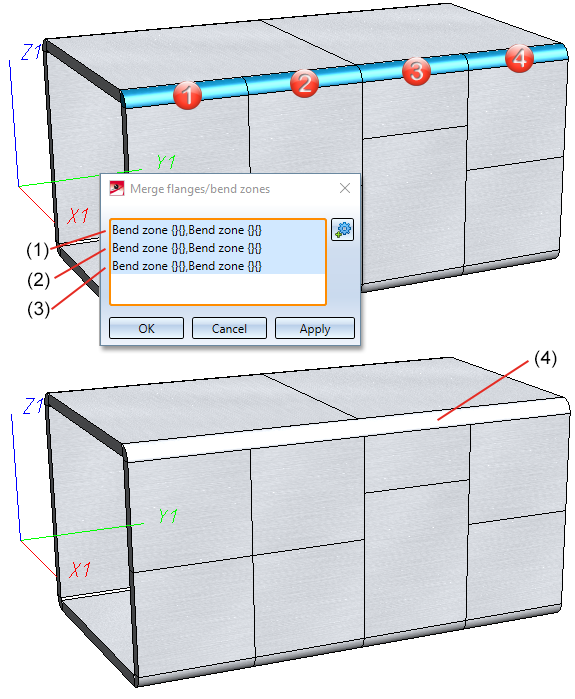
(1) Bend zones 1 and 2 are merged
(2) Bend zones 3 and 4 are merged
(3) Bend zone 2 (previously merged with 1) and 3 (previously merged with 4) are merged
(4) Result
Connect sheets
With the Connect sheets function (Further functions > Extras  > ...), sheet metal parts that have been created with the functions
- Sheet from solid
- Sheet from surface
can also be connected from HiCAD 2022 onwards. The feature log and part structure are merged during the connection.
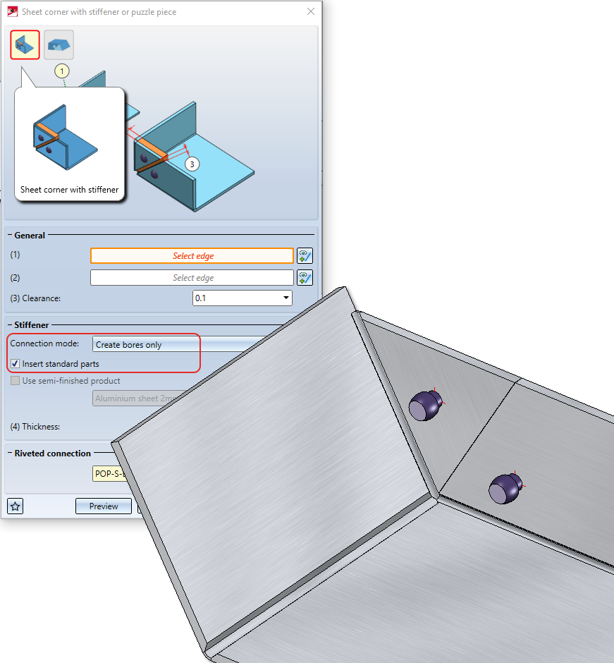
Design Variant "Sheet corner with stiffener"
In the Sheet corner Design variant, you can now insert standard parts without the stiffener.
This means that even though the stiffener and the sheet are not screwed together, the standard parts appear in the bill of materials. To do this, combine the options Create bores only and Insert standard parts.
Change semi-finished material in Feature log
From HiCAD 2200 it is possible to activate the semi-finished product not only via the dialogue but also via the feature log.
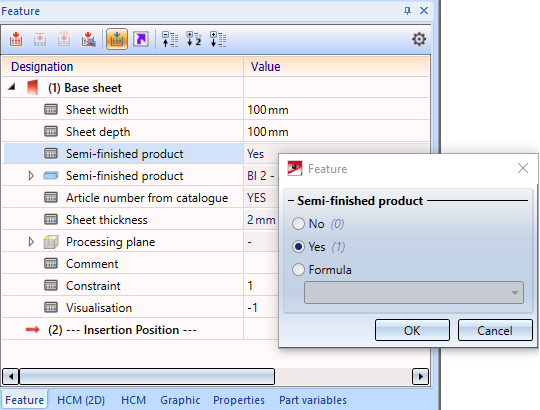
This allows you to change several sheets in one work step, e.g. by assigning variables for assemblies.
New data format for annotations
With HiCAD 2022, the internal data format of labels has changed. When creating new labels, e.g. for sheet metal unwinding, the new format is always used. Visually, there are no differences to the "old" format. If you load a design that contains annotations that were created before HiCAD 2022, a prompt for conversion will appear.
In the Configuration Editor at Compatibility > Annotations > Part annotation, 3-D you can preset how to proceed when constructions with "old" annotation tags are loaded and whether a message is to be output after a conversion.
The conversion of old annotations can also be done automatically by setting the parameter Convert part annotations of the drawing when loading? to Yes, without query.
Coating in sectional views with Steel Engineering plates
As with Sheet Metal parts, from HiCAD 2022 it is also possible to specify for Steel Engineering plates whether the coating is to be marked in the sectional view or not. The marking is done by an offset edge, the so-called coating line. The settings defined in the Configuration Editor at Drawing > Annotations > Coating line in sectional view are used to display the coating line.

HiCAD Sheet Metal • General Notes on Sheet Metal Processing • Overview of Functions (3-D SM)