Basics - What's New?

Discontinuations
Discontinuation of Windows® 7 and Windows® 8Microsoft® has discontinued support for the Windows® 7 operating system in January 2020. For compatibility reasons, HiCAD 2020 SP2 and HELiOS 2020 SP2 were the last versions of our CAD or PDM system to support Windows© 7. HiCAD 2021 and HELiOS 2021 no longer run under Windows© 7, Windows© 8 and the corresponding server operating systems (Windows Server 2008 R2, Windows Server 2012 and older) are also no longer supported. If an attempt is made to install HiCAD 2021 or HELiOS 2021 on a computer with Windows© 7 or Windows© 8, a message appears.
|
Discontinuation of "old" HiCAD itemizationAs of HiCAD 2019 the “old” itemisation, i.e. the itemisation that was used up to HiCAD 2017, will only be available for model drawings that were already itemized with these functions. From HiCAD 2021 onwards, only the “new” itemization will be supported. Please also read the information given in the Conversion of Old Itemisations topic.
|
Discontinuation of "old" OpenGL versionsFrom HiCAD 2021 on, only OpenGL version 4.3 is used in all HiCAD modules. Until now this was only the case with the module HiCAD Point Cloud. This means that HiCAD 2022 can no longer be run on computers without a separate graphics card. To avoid possible problems with onboard graphics cards, we recommend using a stand-alone graphics card.
|
Discontinuation of old figure format (FIG)The following notes regarding FIG-FGA conversion are unnecessary if HELiOS is used in conjunction with the HELiOS Vault Server. Since HiCAD 2017 we support FGA as figure format (before that FIG). From HiCAD/HELiOS 2021 or HELiOS 2021 as an update for HiCAD 2019/2020 onwards, we require that all figures stored with HELiOS have been converted to the new FGA format beforehand. To convert existing 2-D FIG files, the tool Converter_FIG_To_FGA.exe is available in the exe directory of the HiCAD installation. If there are still unconverted FIG files in the HELiOS document database at the time of the database update to HELiOS 2600.0, you will be informed of the outstanding conversion of these files before the database update. In this case, the conversion must be carried out before or at the latest directly after the update using Converter_FIG_To_FGA.exe.
|
Discontinuation of the "old" Create detail drawing functionWith the release of HiCAD 2012, the previously valid workshop drawing functionality in Steel Engineering had been extended to a function for general drawing derivation. The previous functions for detail drawings in Steel Engineering were still available in the Detail drawing section of the Drawing menu. As of HiCAD 2022 (Version 2700.0) these functions are no longer supported.
|
Discontinuation of length measurements deviating from mmHiCAD 2022 only supports drawings with the unit of measurement “Millimetres” (mm). The unit of measurement is saved in the corresponding SZA, FGA or KRA file when saving a drawing or a part. Attempts to open drawings with a different unit of measurement or to insert parts with a unit of measurement different from mm will be blocked.
|
Discontinuation of HELiOS 32-Bit and HiCAD Viewer 32-BitAs of HELiOS 2022 (Version 2700.0), a 32-Bit version for HELiOS and the HiCAD Viewer will no longer be available. However, the interface to 32-Bit applications such as Office will still be possible and is not affected by the discontinuation of the 32-Bit installation of HELiOS.
Discontinuation of CADENAS PARTdataManagerAs of HiCAD 2022 SP2, the CADENAS PARTdataManager will no longer be supported. Thus, the functions Insert main part, PARTsolutions (CADENAS program) and Import PARTsolutions part will no longer be available from SP2 onwards. |
Service Pack 2 2022 (V 2702)
ICN
When calling a function via the context menu of a single part, this part will become the active part. Previously, the part was then additionally marked in blue in the ICN. As of HiCAD 2022 SP2, this colour marking is omitted. This does not apply to a multiple selection of parts!
Update drawing
Rearrange dimensions and annotations
If you have manually created or arranged dimensions or annotations, then as of SP2, you can specify that these dimensions/annotations will be retained when the drawing is updated. The contents will - if necessary - always be updated.
For this purpose, the dialogue window of the Update derived drawing  function has been extended by the Rearrange dimensions and annotations checkbox. If dimensions and annotations are to be retained, you must deactivate the checkbox.
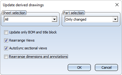
Keeping the dimensions/annotations can only work if the Adjust scale to frame size checkbox is inactive in the drawing derivation.
Please also note the following:
Processing the drawing manually may result in creation or omission of new dimension base points or annotations in the drawing. In such cases, it is not possible to retain the corresponding dimensions and annotations. This means that these dimensions and annotations will be newly created when the drawing is updated and you must subsequently adjust them again accordingly.
Update only BOM and title block
Another new feature of the Update derived drawing function is the Update only BOM and title block checkbox. If this checkbox is active, only the BOM and the title block will be updated. All other changes such as scale, dimensions, designations or new sectional views will not be executed. However, changes to the geometry will be applied.
If this checkbox is active, then all other checkboxes will be inactive.
Workshop drawing - Sheet metal part as assembly main part
Previously, the drawing derivation did not support the automatic generation of workshop drawings for assemblies if the assembly main part was a sheet metal part. As of SP2, this is now possible - but only if the assembly main part is a cassette-shaped or profile-shaped sheet metal part. The procedure for these assemblies is thus analogous to assemblies in Steel Engineering, which have a profile as the assembly main part. The following dimensioning rules have been adjusted for this expansion:
|
Dimensioning rule |
|||
|---|---|---|---|
|
|
Dimensions of assemblies, |
||
|
2 |
Assembly length |
ASSEMBLYLENGTH |
|
|
19 |
Assembly height |
ASSEMBLY_HEIGHT |
|
|
20 |
Assembly width |
ASSEMBLY_WIDTH |
|
|
|
Position of beam sub-parts |
||
|
8 |
Attached parts via outer contour |
ATTACHING_PARTS |
* |
|
10 |
Attached sheets/plates with bores |
ATTACHING_SHEETS |
* |
|
57 |
Attached plates, one chain of dimension for each plate |
ATTACHING_SHEETS_SEPERATELY |
* |
|
83 |
Attached plates with bores, incl. bore in side view |
ATTACHING_SHEETS_VERT |
* |
|
117 |
Beam sub-parts, not vertical to main part axis |
ATTACHING_PROFILES |
* |
|
70 |
Attached beams/profiles with axis, to main part axis, dimension via system axis |
ATTACHING_PROFILES_VERT |
* |
|
|
Position of bores in sub-parts |
||
|
11 |
Bores in sub-parts |
SUBPARTBORES |
|
|
84 |
Bores in sub-parts (bores of all sub-parts) incl. bores + viewing direction |
SUBPART_BORES_VERT |
|
|
89 |
All parts via bore |
ALL_PARTS_BORES |
|
|
|
Dimensions of bores/hatchings in the main part |
||
|
45 |
Diameter of standard part bores in main part |
NORMBORE_DIAMETER_MAINPART |
|
|
44 |
Diameter of simple bores in main part |
BORE_DIAMETER_MAINPART |
|
| 46 |
Diameter of boltings in main part |
CONNECTION_DIAMETER_MAINPART |
|
* Here, the Dimensioning settings  function under Bores / Boltings > Chains of dimensions for sub-parts can also be used to control whether the first, the last or the first and last bore will be used for dimensioning.
Itemisation - Sorting by article attributes
On the Attributes tab of the Itemisation with options  function, you specify which attributes are to be taken into account during identical part search and itemisation. As of SP2, a distinction is now made here between HiCAD part attributes and HELiOS article attributes, whereby the individually indicated HELiOS article attributes are used exclusively for sorting. The criterion for the differentiation is always the article master itself (usually the article number + index).
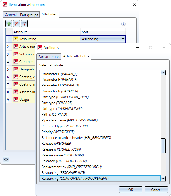
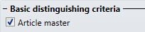
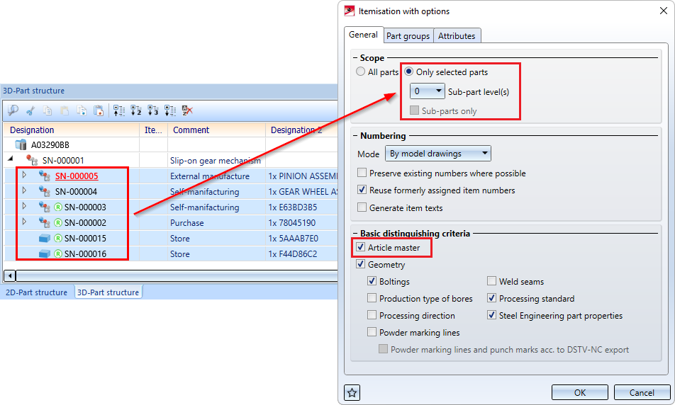
However, article attributes can only be selected if the Article master checkbox is activated on the General tab.
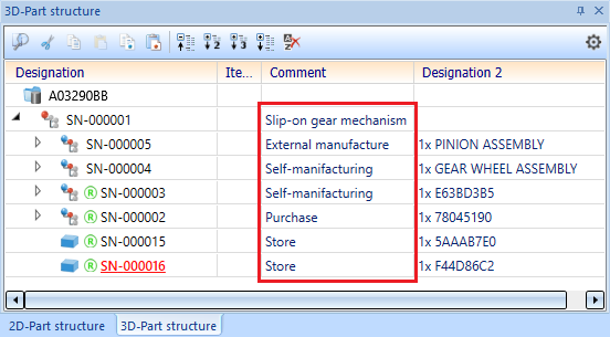
In this example the article attribute Resourcing (COMPONENT_PROCUREMENT) is to be used as a sorting criterion.
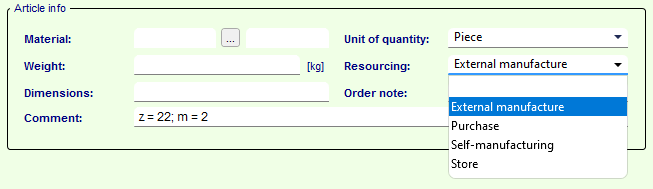
The drawing consists of 6 assemblies with different resourcing characteristics.
For the sake of clarity, in this example we select the six assemblies in the ICN and then call the Itemisation with options function.
On the General tab we select the settings shown.
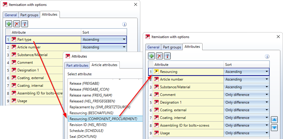
On the Attributes tab we select the article attribute Resourcing (COMPONENT_PROCUREMENT) instead of the part attribute Part type.
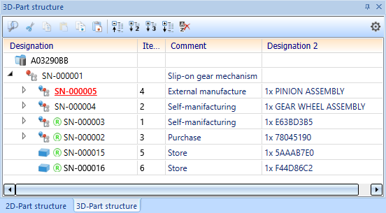
The itemisation then gives the following result:
Service Pack 1 2022 (V 2701)
Performance
Acceleration when zooming in with the mouse wheel
Analogously to the accelerated rotation of shaded representations, zooming in with the mouse wheel is now also significantly faster in HiCAD 2022 SP1.
During a test with a customer drawing consisting of approximately 560.000 parts, zooming in in HiCAD 2022 took only 6 seconds - compared to 14 seconds in HiCAD 2021.
Part selection
Previously, it was possible to move from one part within the part structure to the next higher and thus higher-ranking part by holding down the left mouse button and then pressing the right mouse button during Part selection in the drawing. As of SP1 this also applies vice versa.
If you press the middle mouse button instead of the right mouse button while holding the left mouse button, you will return to the previously marked element in the part structure.

Itemisation
Variable through holes
In previous HiCAD versions, incorrect results could occur in certain situations when comparing variable through holes, for example if holes were drilled in opposite directions. These were recognised as different if their base points did not match. As of HiCAD 2022 SP1, this behaviour has changed. This means that if the distances between the start and the end of the drilling cylinder are equal, then the bores are considered equal. An exception are bores that are only displayed as axes.
Let us look at the example displayed below. There, the part is present four times in the drawing. In all four parts, a variable through hole was inserted which goes all the way through the part. Parts (1) and (3) were drilled from the top to the bottom, parts (2) and (4) were drilled the other way around. The base point is always the centroid of the entry surface. In (1) and (2) the bore is accurately displayed, in (3) and (4) only the axes are displayed.
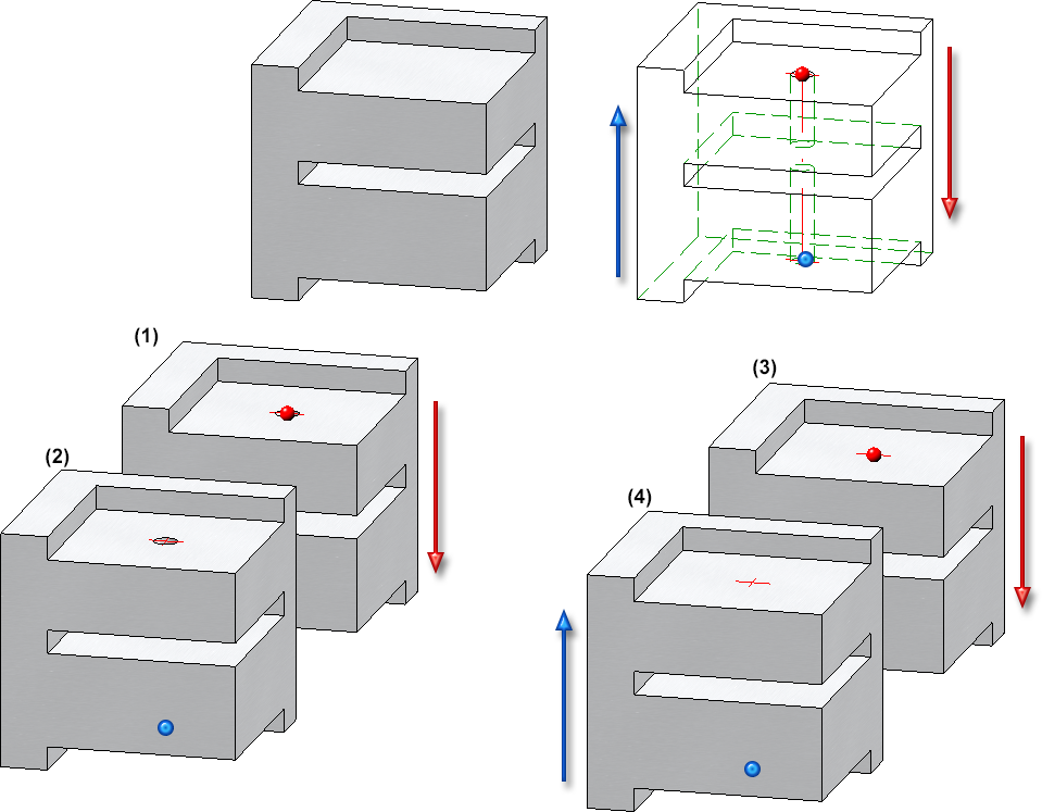
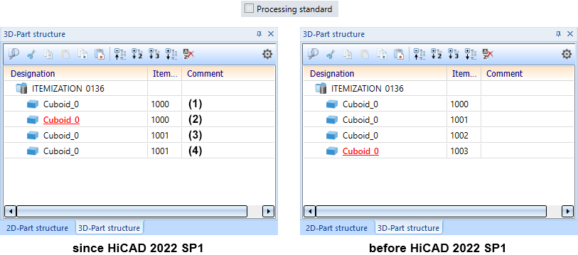
If the itemisation is now carried out, then parts (1) and (2) will be considered to be equal despite the different hole directions. The same applies to parts (3) and (4). Parts (3) and (4) therefore have a different item number than (1) and (2) because only the axes of the bore are displayed here.
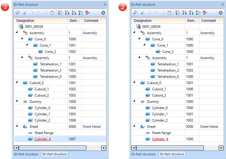
Sub-parts of sheet metal parts
With HiCAD 2021, the possibility of itemising sub-parts of a sheet metal part in the part structure has been removed. However, this has proved to be problematic in some customer drawings. Therefore, this behaviour is reversed with HiCAD 2022 SP1.
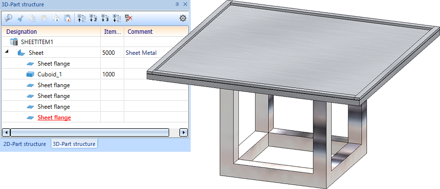
In other words, parts that are sub-parts of a sheet metal part will be itemised again (if they are BOM-relevant). However, this does not apply to flanges and bend zones. These are generally not itemised.
In the following image, the cuboid is subordinated to the sheet metal part as a sub-part and is therefore itemised, unlike the flanges of the sheet.
Treat regular parts like assemblies
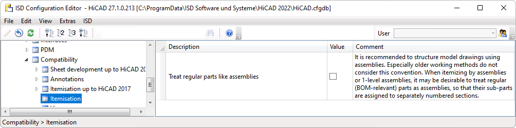
To create a clear and efficient drawing, assemblies should be used for structuring. However, this is often not taken into account, especially in "older" ways of working. Here it can sometimes be desirable to treat regular (BOM-relevant) parts like assemblies during the itemisation, so that their sub-parts become separately numbered sections. For these cases, the checkbox Treat regular parts like assemblies is available as of SP1 in the Configuration Editor under Compatibility > Itemisation.
If the checkbox is active, regular (BOM-relevant) parts will be treated like assemblies during the itemisation in HiCAD and their sub-parts will become separately numbered sections. The prerequisite is that you have selected the mode by assemblies or - if a main assembly exists - by top level assemblies in the itemisation settings on the General tab.
(1) Do not treat regular BOM-relevant parts like assemblies, (2) Treat regular BOM-relevant parts like assemblies
Derived drawings
Sectional views of sheet metal parts
The generation of the section path during the automatic drawing derivation of sheet metal parts has been optimised in HiCAD 2022 SP1.
- Processings that are located on the outer edges are now taken into account when determining the position of the section path of sheet metal parts.
- Sectional views are generated at all bend zones of the flanges that are parallel to the defined front view (part orientation).
see also Sheet Metal - What's new?
Major Release 2022 (V 2700)
Licensing
As of HiCAD 2022, the Plot Manager is part of the HiCAD ALUCOBOND® Suite Premium.
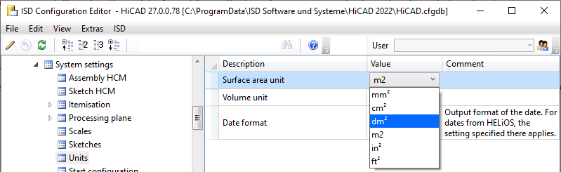
Units
It is now possible to specify decimetres as the value for the surface and surface area unit. For this purpose, the selection box in the Configuration Editor has been expanded accordingly.
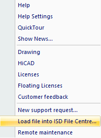
Uploading files into the ISD File Centre
From HiCAD 2022 onwards, you have the possibility to upload files directly from HiCAD if you are using the ISD File Centre for data exchange with the ISD Support. For this purpose, the new Load file into ISD File Centre function can be found in the Help menu.
Multiple selection of Features and HCM-constraints
Analogous to the multiple selection of parts,the multiple selection of features or HCM constraints can now also be cancelled by left-clicking in an empty area of the ICN or the drawing.
Line breaks when editing formulas
When using the Edit formula function, it is now possible to insert line breaks in formulas by using the key combination SHIFT-ENTER. This allows you to distribute extensive formulas across several lines.
Limiting angle for shading
In previous HiCAD versions, the Limiting angle for shading function ensured that non-tangential transitions appeared rounded in the shaded view. This function is no longer needed and thus has been removed. This applies to both the drawing properties and the properties of 3-D parts.
Import of HASCO and STRACK standard parts
The functions for inserting HASCO and STRACK standard parts have been removed from the HiCAD user interface with HiCAD 2021 SP1. As of HiCAD 2022, importing via the macros and via the API will also no longer be possible!
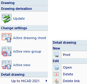
Creating detail drawings
With HiCAD 2012, the previously valid functionality for creating workshop drawings in steel engineering has been expanded to a function for general drawing derivation. For compatibility purposes, the previously available functions for detail drawings in steel engineering were still available under Detail drawing in the Drawing menu. As of HiCAD 2022 (Version 2700.0), the previous functions for creating detail drawings will no longer be supported.
|
|
Create detail drawing for selected SE parts |
|
|
Create + Print detail drawing |


Use the Derive drawing function to create detail drawings.
However, in some cases the other functions can still prove useful for old drawings. Therefore, these functions were combined in a separate submenu, under Drawing derivation > Up to HiCAD 2021.
Enhancement when switching to standard itemisation since HiCAD 2018
Since HiCAD 2021, the Itemisation up to HiCAD 2017 mode is no longer available. In drawings that were created with an earlier HiCAD version and - at least partially - itemised with the old itemisation mode, the previous itemisation must be converted accordingly before using the itemisation functionality in HiCAD 2021.
The following should be noted:
Since HiCAD 2021, it has been possible to define when bores are considered to be equal for identical part search during the itemisation. For this purpose, the Processing standard checkbox is available in the dialogue window of the General tab.
|
|
Bores - including those created as subtractions - are considered to be equal, even if they are represented differently. An exception to this are bores that are only represented as axes. |
|
|
Bores and corresponding processings are only considered equal if their catalogue/table IDs match. |
 Processing standard
 Processing standard
To avoid "surprises" when migrating inventory data, the new Activate the new option 'Processing standard' when loading the itemisation settings from legacy data switch is available under System settings > Itemisation > Migration in the Configuration Editor.
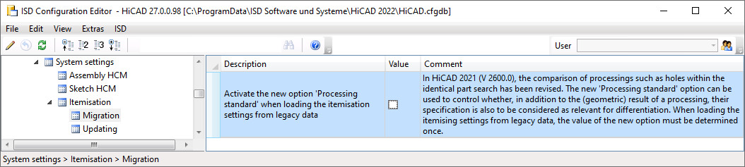
If the switch is active, the Processing standard checkbox in the itemisation settings for the conversion is activated. Otherwise it is deactivated.
This way you can convert your inventory data with and without considering the processing standard, compare the results and thus find the right setting for your drawing.
Derived drawings
Settings for view groups
The distance between views of a view group is automatically determined in such a way during the drawing derivation that the result is a drawing that is as appealing as possible. However, under Automatic drawing derivation > Production drawing > Usage-dependent > ... > View group in the Configuration Editor, you can set the minimal distance to be developed between the views. This is particularly important if it is already clear in advance that additional annotations will have to be added to the drawing and that a certain distance will be required for this.
Deleting sectional views
Manually deleted sectional views of a workshop drawing remain deleted, even when the drawing is updated. However, this only affects the respective view group the sectional view was deleted from. If other drawings exist for the corresponding part, the sectional views in this view group are unaffected.
 If the sectional view of a double stiffener is deleted, the two stiffeners will not receive a sectional view, even as single stiffeners.
Shortened views
Since HiCAD 2020 SP1, the shortening of views is also possible for shaded views (Representation Shaded with/without edges or Quick HiddenLine / Quick Hidden Grey), whereas the shortening marks are displayed in the colour selected in the shortening parameters for break lines. This also applies to the shortening of shaded views in workshop drawings.
Linking the axonometry to the main view
In workshop drawings where multiple assemblies are given out on one sheet, the axonometry is now linked to the corresponding assembly's master view. If only one assembly is presented on the sheet, this does not apply.
Which view becomes the master view depends on the views selected for assemblies. The master view is determined in the following order:
Front view ⃗ Back view ⃗ Top view ⃗ Bottom view
If the front view is selected, it will become the master view. If it is not selected, the system will examine if the back view has been selected. If so, this view will become the master view, etc.
Moving the master view will result in all of the linked views likewise moving.
Maintaining the perspective of axonometric views
If the perspective of an axonometric view is changed in a workshop drawing that was created with the Derive drawing function, e.g. by rotating the view, the perspective will be maintained even when the drawing is updated. Automatically created shortenings are recalculated accordingly. However, manually created shortenings will not be retained.
Consideration of the numbering mode during itemisation
If the By assembliesnumbering mode is selected during the itemisation, then the identical part search and the assignment of item numbers will take place within the assembly. It may happen that two different parts from two different assemblies are given the same item number.
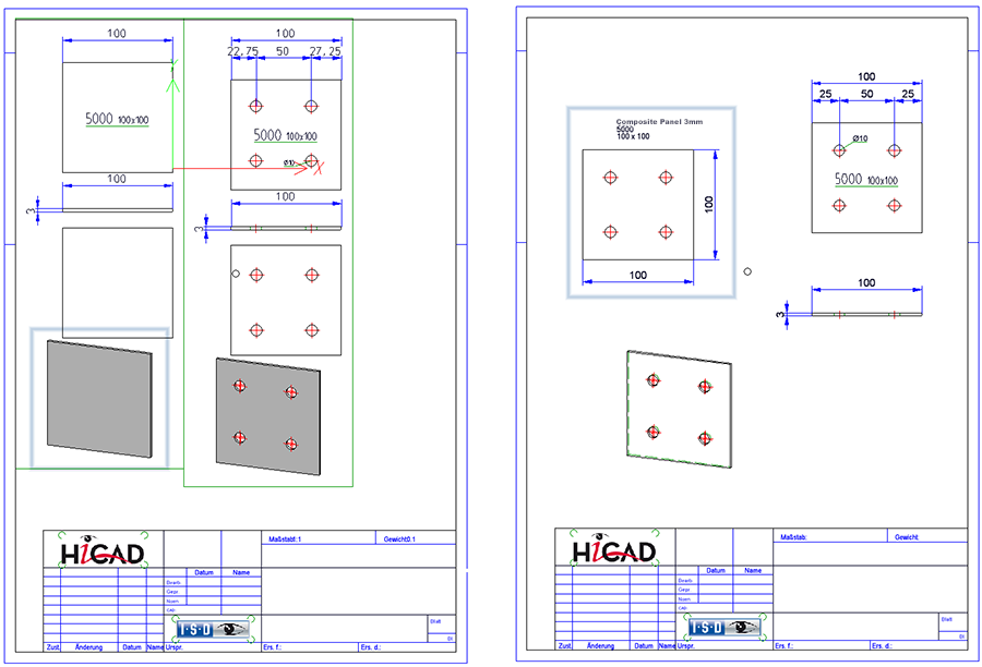
Previously, when creating a workshop drawing, only one of the two parts was output and detailed in cases like this. As of HiCAD 2022, the numbering mode of the itemisation will be taken into account during drawing derivation. This means that the parts will no longer be compared only according to the item numbers but also according to the level of the part structure.
Example:
The drawing illustrated here consists of two assemblies, each including a composite panel, one of which contains bores. If this drawing is itemised by assemblies, both composite panels - although different - will receive the same item number.
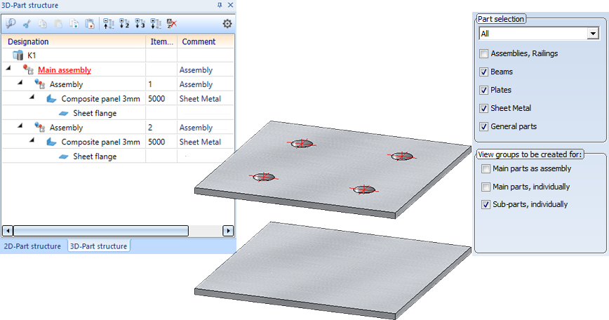
Now the drawing is created via the settings shown at the top right. The following illustration shows the drawing created with HiCAD 2022 on the left and the drawing created with HiCAD 2021 on the right.
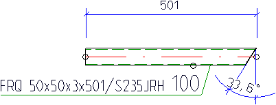
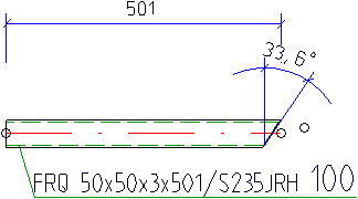
Direction of angular dimensioning
When using the automatic drawing derivation, the angle for cuts, e.g. for profiles, was previously always dimensioned on the outside of the part. As of HiCAD 2022, it is now possible to specify whether the dimensions are to be created inside or outside for angular dimensions of cuts.
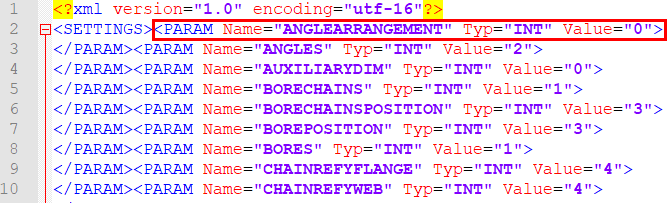
The setting can be changed in the STWDimsettings.xml file in the HiCAD SYS directory, in the line
<PARAM Name="ANGLEARRANGEMENT" Typ="INT" Value="0">
|
Value="0" |
outside |
|
|
Value="1" |
inside |
|
When HiCAD is newly installed, the STWDimsettings.xml file will automatically be created when starting HiCAD for the first time - including the new line.
For update installations, you must add the new line to the existing file. There are two ways of doing this:
- You delete the existing STWDimsettings.xml file. The next time HiCAD is started, the file will be recreated with the new line.
- You add the line manually.
Total quantity attribute
Since HiCAD 2021 SP1, it has been possible to determine how often each part exists in the drawing during the itemisation. This value is assigned to the Total quantity (%06) attribute. Previously, this was only possible if the By model drawing mode was selected as numbering mode for the itemisation.
As of HiCAD 2022, the total quantity is now also calculated if By assembly is selected as the numbering mode. This means that if the drawing contains multiple identical assemblies (on the same hierarchical level), their total quantity in the drawing is determined. For the parts belonging to an assembly, the total quantity within the assembly is determined.
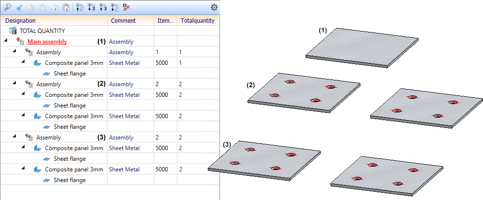
Example:
The illustrated drawing consists of three assemblies (1) to (3). Assemblies (2) and (3) are identical and receive the same item number. The total number of assemblies with item number 2 is 2. The other parts are counted by assembly, i.e. the total number of perforated sheets per assembly is 2.
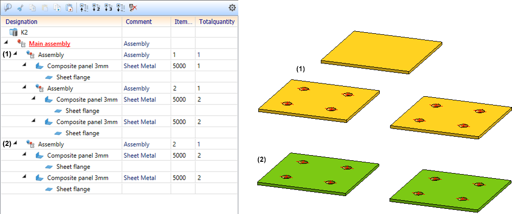
In contrast, let us consider the following drawing, consisting of two assemblies (1) and (2). A copy (3) of assembly (2) is subordinated to assembly (1). When itemising by assembly, the assemblies (2) and (3) will receive the same item number, but since the two assemblies are not on the same hierarchical level, their total quantity is 1.
If the total quantity is to be calculated during the itemisation, then the Calculate total quantity checkbox must be active under Modelling > Part properties in the Configuration Editor.
If the checkbox is active, the number of times each part appears in the model drawing is determined during itemisation (only in itemisation mode By model drawings). This value is assigned to the attribute Total quantity (%06) and automatically updated when editing the parts, e.g. when deleting or repeating parts. In very large constructions, this update can have a negative impact on performance, for example when deleting assemblies. In such cases, the checkbox can be deactivated. If this is the case, then - after a restart of HiCAD - the next time the drawing is loaded, the attribute Total number of the affected parts will be deleted instead of calculated.
Saving/Referencing parts
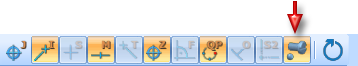
The dialogue of the Reference part, Save, Detail drawing  function has been altered slightly.
- The texts in the Referance part section have been adjusted.
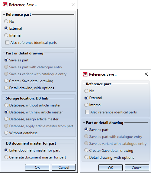
Dialogue with and without HELiOS
-
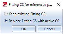
The prompt regarding the Fitting CS now appears before the selection of the storage folder. The prompt only appears if a Fitting CS is already in place at the time of referencing.
Path for referenced parts
The Path for referenced parts function in the Drawing > Extras > Temporary settings menu is no longer available. To change the path for referenced parts, open the Settings in HiCAD and adjust the folder for the L: identifier under Directories. Then restart HiCAD to let this setting become active. The change is related to one specific workplace and may have to be carried out on all other workplaces as well.
Saving the ICN display with the drawing
HiCAD offers the possibility to save the ICN display together with the drawing. In this way, the HELiOS attributes are also displayed in the part structure of the HiCAD Viewer. It is either possible to temporarily perform the setting during the current HiCAD session or set it as a default setting in the Configuration Editor.
Sometimes generating the ICN can lead to considerable waiting times. As of HiCAD 2022, if the Save ICN display with drawing status is active, the new message
Save drawing (generate ICN designations for Viewer)
will be displayed in the user guidance (info toolbar) during the saving process. This enables you to see that the status is active and could possibly be the cause of the waiting time.
Standard part points
In previous HiCAD versions, it could happen that dimension base points on standard parts were lost if, for example, the representation was changed from exact to simple or another standard part type (e.g. screw of another standard) was changed.
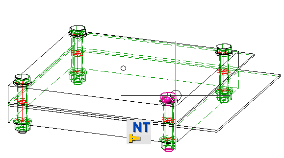
For this reason, the Standard part point option is available as of HiCAD 2022. This point option provides the origin of the part coordinate system of standard parts, which remains stable even when standard parts are exchanged.
The point option cannot be activated via the point option menu. Instead, the following activation options are available:
- If a dimensioning or annotation function is active, the point option can be selected via the Autopilot, provided it is active in the Autopilot Settings toolbar.
- In other functions, the point option can be used as follows:
- Move the cursor over the corresponding standard part.
- Activate the Point options menu.
- Select the point option Input via keyboard
 and enter NT. Then the point on the part under your cursor will be determined.
