Plant Engineering - What's New?

Service Pack 2 2022 (V 2702)
Discontinuation of the Import PartSolutions part function
As of HiCAD 2022 SP2, the function Import PartSolutions part is no longer available.
Delete several parts - Saving of dialogue settings
The dialogue settings of the Delete several parts  function were previously always retained only for the current HiCAD session.
From HiCAD 2022 SP2 onwards, the settings are saved when the dialogue is closed with OK and are preset the next time the dialogue is opened. This does not only apply to the current HiCAD session. Please note, however, that the settings under Additional conditions are not taken into account!
Automatic flow assignment during automatic part insertion
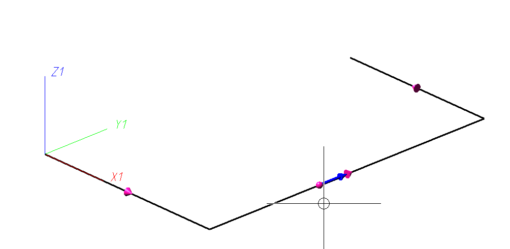
When using the AutoPlace parts on guidelines  function, a consistent flow at the corners of the guideline is important, especially when placing knees, because the flow direction affects the insertion direction.
Accordingly, this function checks whether the flow is consistent. If this is not the case, the function was previously aborted with a corresponding message and the corresponding point was marked with an arrow.
As of HiCAD 2022 SP2, you have the option to have the flow direction corrected automatically in such cases. The following message is displayed for this purpose:
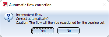
If you select Yes, HiCAD automatically reassigns the flow, i.e. overwrites it. The input dialogue then starts again from the beginning.
If you select No, the function is terminated and the position where the inconsistency exists is marked with an arrow as before.
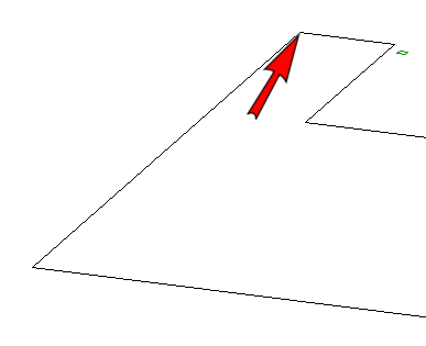
If necessary, you can then correct the flow yourself using the Edit flow function.
Insert pipe clamp as sub-part
With the new Pipe parts  function , it was previously not possible to place a pipe clamp freely in space. In the event that the pipe clamp is to be inserted as a sub-part of a fixed superordinate part, this restriction has been removed as of HiCAD 2022 SP2. In this case, the pipe clamp is not part of a pipeline, so free placement does not create an invalid pipeline structure.
Sheet number at transitions of divided isometries
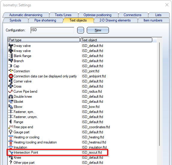
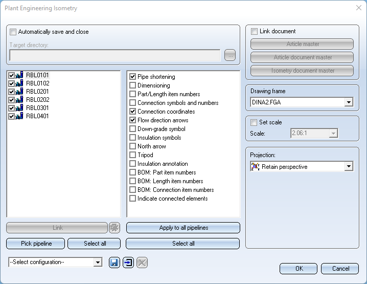
An isometric drawing can be divided into several sheets by assigning division points. For annotating the intersections (i.e. the division points in the isometry) there is a special text object type ISD_ISOCUT.FTD, which can be configured in the isometry settings like the other text object types. In this way, the annotations are generated automatically when the isometry is created.
Useful as annotations are for example
- the coordinates (attribute %PIPE_X_COOR) or
- the division index (attribute %PIPE_ISOSPLIT_IDX).
The division index can be used to directly read where the isometric drawing is continued. However, the division index has no direct reference to the sheet number. Especially when there are many subdivisions, finding the next partial drawing can sometimes be rather difficult.
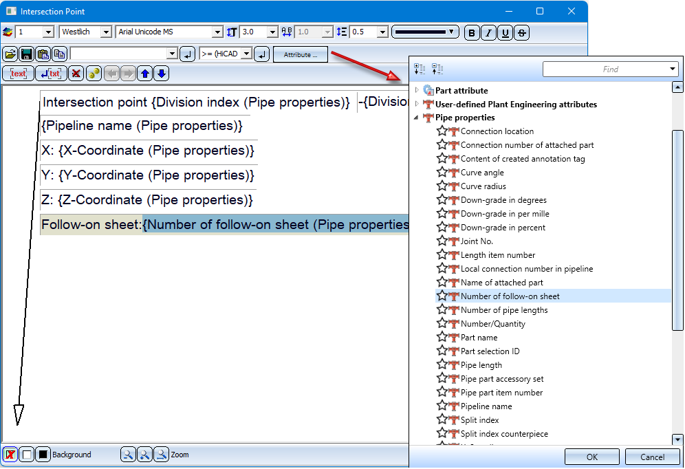
As of HiCAD 2022 SP2, the output of the Number of follow-on sheet (attribute %ISO_CONTINUED_ON) is useful here. This attribute refers directly to the sheet on which the isometric drawing is continued.
For annotating the intersections (i.e. the separation points in the isometry) there is a special text object type ISD_ISOCUT.FTD, which can be configured in the isometry settings like the other text object types. In this way, the annotations are generated automatically when the isometry is created.
To make it even easier to follow the sequence of the sheets containing the partial drawings, HiCAD additionally takes into account the flow at the division points and thus determines the sequence of the sheets.
Example:
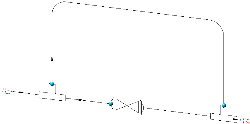
In the isometry shown below, three division points are defined and then the isometry is recreated for the three resulting sections.
The sequence of the sheets is based on the flow between the different sections.
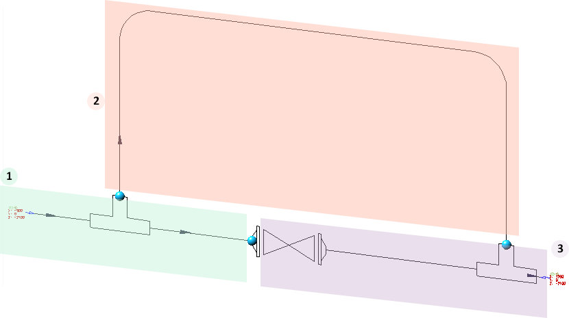
Generally, the longest path between the sections is determined that follows the flow. However, this only works if the flow through the sections is directed and acyclic, i.e. has no circles. Otherwise, the leaf sequence is determined arbitrarily by HiCAD. In the above example, however, the flow meets the requirements and the result then looks as follows:
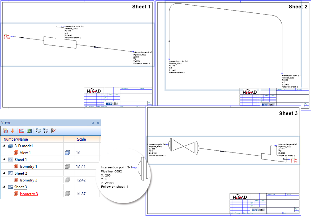
The number of the follow-on sheet (attribute %ISO_CONTINUED_ON) is not preset on the ISD side in the file the ISD_ISOCUT.FTD. If the attribute is to be output in the partial drawings of the isometry, you must adjust the FTD file manually.
Search and replace in variants
A variant is described by various attributes, some of which are identical or almost identical for all sub-types. Examples of this are the file name or the order note.
In practice, it can happen that a series of attributes must be changed in several variants. In this case, it would be very time-consuming to open and adjust each variant individually.
In this case, the Variant Editor offers the possibility of searching several variants for an attribute and replacing the current value with another one.
The Search & Replace is done via the command line call of the Variant Editor with the call parameter searchAndReplace.
Derive pipe class with content
As of SP2 a new function for pipe classes is available in the HELiOS Desktop: Derive pipe class ... . Use this function to create a copy of the pipe class including all its sub-types.
Variants can be taken over in their current state or can be derived and assigned to the new pipe class. (see also HELiOS Desktop - What's new?)
Service Pack 1 2022 (V 2701)
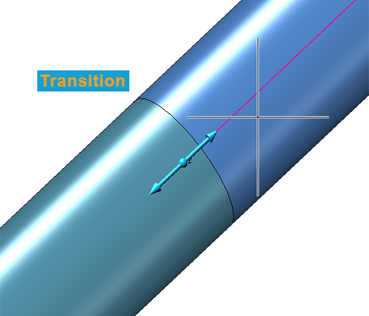
Dynamic route change - Pipeline transitions
If you move the cursor over a pipeline transition during the dynamic route change, a corresponding note will now be displayed. This is the case when two pipelines meet.
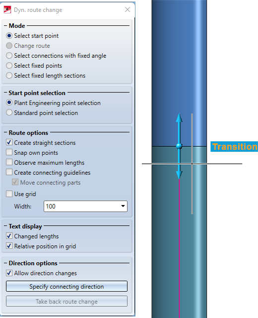
The info text is always placed at the outer diameter of the pipes at the pipe transition. This is independent of how the view is rotated.
Insert pipe part
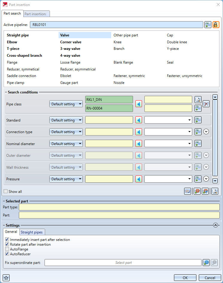
The function Pipe parts has been extended.
Active pipeline
The name of the active pipeline is now displayed in the upper area of the tab.
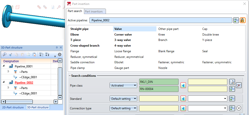
Newly added parts will be subordinated to this pipeline, provided there is nothing to the contrary, e.g. the placing of a part on a guideline. In such a case, the part must be assigned to the same pipeline as the guideline.
You can change the active pipeline within the dialogue. To do this, click on the  symbol and then select a pipeline in the drawing or in the ICN.
If you click in the name field, the active pipeline is highlighted in the drawing. Clicking again removes the highlighting.
Displaying and selecting the active pipeline in the dialogue makes it easier to connect parts to existing pipelines if the new part to be inserted is to be assigned to another pipeline.
If you want to define the pipeline assignment depending on the connecting point (standard behaviour before HiCAD 2022 SP1), click on the symbol. The  symbol changes to
  and the active pipeline is no longer fixed but follows the connecting point.
Also note that the pipe class suggested in the search criteria now follows the active pipeline.
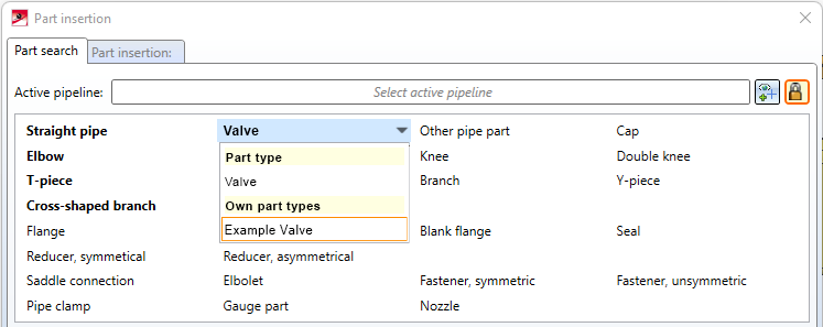
Select own part type
If you have defined your own part types, e.g. valves, an arrow symbol is displayed next to the part type. Clicking on the symbol displays a list box with the corresponding part types.
Show flow direction
When inserting parts, the flow direction is now shown on the guidelines. The flow direction arrows are always shown on the guideline over which the mouse has been moved.
Automatic loose flange insertion
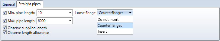
The settings in the dialogue window have been adjusted. The Divisible pipes tab has been renamed and an option for loose flange insertion has been added. This setting corresponds to the setting for automatic loose flange insertion on the Straight pipes tab in the Plant Engineering settings.
Reference part filter
The selection of a reference part in the new part dialogue has been extended by an additional button  with which you can filter the selection by the active part type.
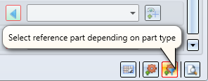
This button is only available if a part type is selected at the top of the dialogue. In contrast to the usual selection of a reference part, only a part with the selected part type can be selected.
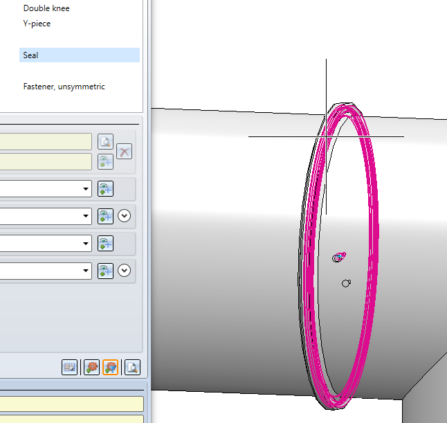
This selection mode is intended for parts that are difficult to select without narrowing the part type. For example, a gasket may be completely hidden by a fastener. Through the filtered selection, though, it can still be selected.
BOM-relevance of manually inserted gaskets
If the Plant Engineering setting Flange gasket: Do not consider was active, then manually inserted gaskets were not BOM-relevant until now. They were listed as accessories in the flange, but not in the BOMs. As of HICAD 2022 SP1, these gaskets are always BOM-relevant.
EN 10241 - Additional threaded parts
The range of parts in HICAD has been extended by the following variants:
- Nozzles
- EN10241_WELDED_NIPPLE_R208_1.VAA
- Sadddle connections
- EN10241_WELDED_NIPPLE_R208_2.VAA
- Other pipe parts
- EN10241_NIPPLE_R210.VAA
- EN10241_SOCKET_R201.VAA
- EN10241_WELDED_NIPPLE_R208.VAA
- MUFFE_DIN2986.VAA (previously only available as nozzle)
- NIPPEL_DIN2982.VAA (previously only available as nozzle)
Isometry / Pipe spool drawing -Existing article masters
In the Configuration Editor at Plant Engineering > Isometry and Pipe spool drawing the parameter Show pipeline article for editing can now be used to determine whether the article mask of the pipelines should be displayed or not before generating the isometry/pipe spool drawing
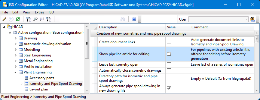
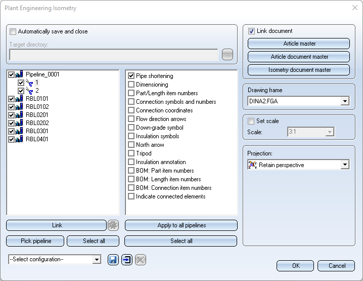
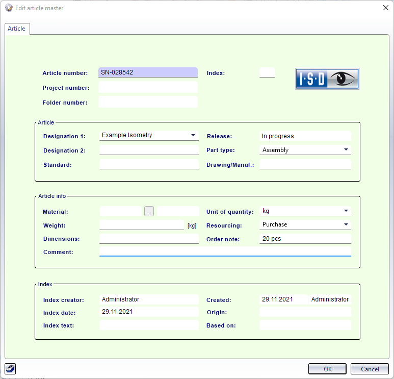
Activating the parameter has the following effect when calling the function AutoGenerate drawing / Generate pipe spool drawing: If the pipelines to be derived are selected in the dialogue and the checkbox Link document is active, the Edit article master mask is displayed for each selected pipeline so that you can adjust the data if necessary.
Major Release 2022 (V 2700)
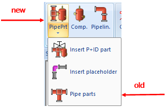
New part insertion function
The Pipe parts function for inserting parts in Plant Engineering has been completely revised.
In this dialogue window you have full control over which search criteria are used to find a part.
The previous function for the installation of pipe parts is still available.
A separate function is now available for the insertion of P+ID parts:

Please note that not all Plant Engineering settings are relevant for the new part insertion function. This is marked accordingly on the corresponding help pages.
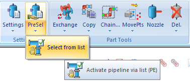
Activate pipeline via list
Since HiCAD 2020 (V 2500), the active pipeline is determined via the active part. This means: If the active part belongs to a pipeline, then this pipeline is considered to be an active pipeline. Otherwise, no pipeline is active.
Up to HiCAD 2019, the pipeline could also be selected via the list of all pipelines using the Activate pipeline via list  function. This function was "reactivated" again with HiCAD 2022. In contrast to the previous function, however, the selected pipeline now becomes the active part. You can find the function at Plant Engineering > Settings > PreSel.
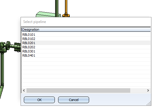
A pipeline that is already active before the start of the function is initially highlighted in grey.
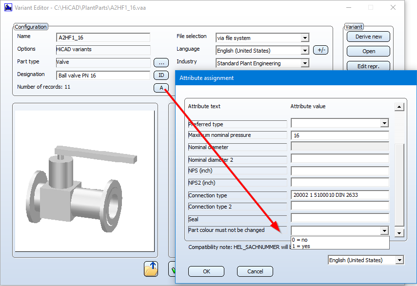
Parts with unchangeable colour
The colour of parts added to a pipeline depends on the Plant Engineering Settings for Part insertion. If the checkbox Take over pipeline colour is active there, the part receives the current colour of the pipeline, to be more precise, of the part ~parts of the pipeline. If the checkbox is inactive, the part receives the current surface colour set in HiCAD.
Sometimes, however, it is desirable - especially with elaborate parts - if they retained their original colours during insertion. For example, the different areas of complex valve parts may have been coloured according to their function.
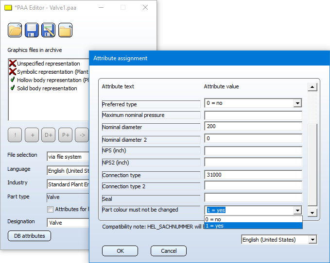
In order to mark such parts accordingly, an additional part attribute is available that specifies whether the colour of a part may be changed during insertion:
|
Attribute designation |
Attribute name HiCAD |
Attribute name HELiOS |
|---|---|---|
|
Part colour must not be changed |
FIXCOL |
FIXED_COLOR |
In order for this attribute to be available for the different part types, the file nnnnnnn.CatSearchAtt.txt belonging to a part type in the HiCAD subdirectory PlantParts\CatSearch must be extended by the line
S:FIXED_COLOR,
with nnnnnnn is the part type identifier.
This has already been preset for the following part types:
|
Part type |
|
|---|---|
|
3-way valve |
4300010.CatSearchAtt.txt |
|
Corner valve |
4200010.CatSearchAtt.txt |
|
4-way valve |
4400010.CatSearchAtt.txt |
|
Valve |
4100010.CatSearchAtt.txt |
|
Pipe clamp |
5810010.CatSearchAtt.txt |
|
Other pipe part |
5900010.CatSearchAtt.txt |
|
Gauge part |
5920010.CatSearchAtt.txt |
If, for example, you also want to use this attribute for Saddle connector, you must adapt the file 6110010.CatSearchAtt.txt accordingly.
The attribute can be assigned to parts in the variant editor and in the PAA Editor.
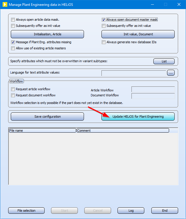
To make this attribute available in your HELiOS database, you must first update HELiOS for Plant Engineering.
Please note:
The attribute only applies to the insertion of parts. If the pipe colour is subsequently changed, the colour of the parts added to the pipe is also changed.
Pipeline planning - Article attribute for length allowance
The Pipeline planning functionality supports the Length allowance attribute for pipe parts. This allows you to specify that a part is actually longer than the insertion length. An application case is pipes that are provided with a loose flange before insertion and then flanged. The flanging of the pipe reduces the insertion length, but the pipe must be ordered in the original length.
|
Attribute designation |
Attribute name HiCAD |
Attribute name HELiOS |
|---|---|---|
|
Length allowance |
ADDLENFIXCOL |
PIPE_ADDED_LENGTHFIXED_COLOR |
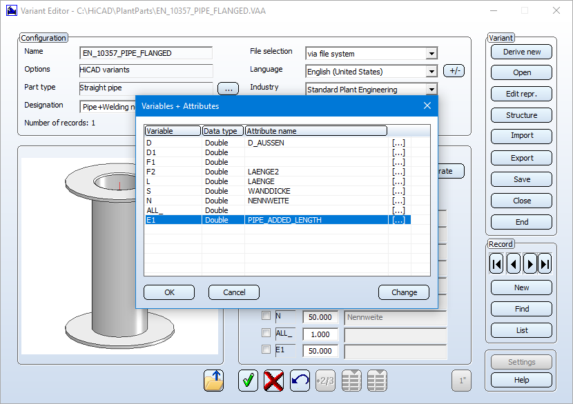
To use the length allowance, you must adapt your variant file or the parts archive accordingly. You thus determine which values are transferred to the length allowance during part data synchronisation. In the example of a variant shown, this is part variable E1:
After inserting a part, you will find the entry Length allowance in the drawing in the part information, if such an entry is available on the part:
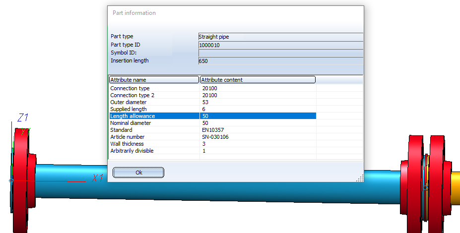
This pipe has an insertion length of 650 and a length allowance of 50. It was inserted with the following settings for straight pipes:
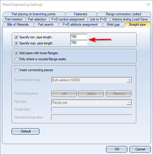
The maximum pipe length as of HiCAD 2022 is equal to the insertion length plus the length allowance. If you use pipes with and without length allowance in your drawings, you do not have to worry if the maximum length that can be installed does not match the maximum length that can be ordered.
Similarly, the HELiOS attribute Supplied length also affects the installable maximum length by deducting the length allowance.
 The length allowance is taken into account in the Total length column of the layout plan BOMs.
New variants for flared pipes
The following four variants have been added to the pipe part inventory:
- EN10357_PIPE_BEADED_BOTH_PN10_FME4.VAA
- EN10357_PIPE_BEADED_BOTH_PN10_FME8.VAA
- EN10357_PIPE_BEADED_SINGLE_PN10_FME4.VAA
- EN10357_PIPE_BEADED_SINGLE_PN10_FME8.VAA
These are flared pipes, whereby the SINGLE variants are only flared at connection point 1 and the BOTH variants are flared at both connecting points.
All variants use the new Length allowance attribute.
Isometric drawings and pipe spool drawings - - Article attribute for length allowance
In the BOMs of isometric drawings and pipe spool drawings, too, the length allowance is taken into account.
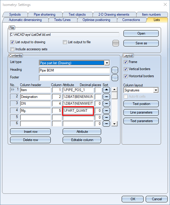
The columns in these BOMs are filled via configurable text keys, of which the following evaluate the length allowance from HiCAD 2022 onwards:
|
%PART_QUANT |
Returns the insertion length plus the length allowance for straight pipes |
|
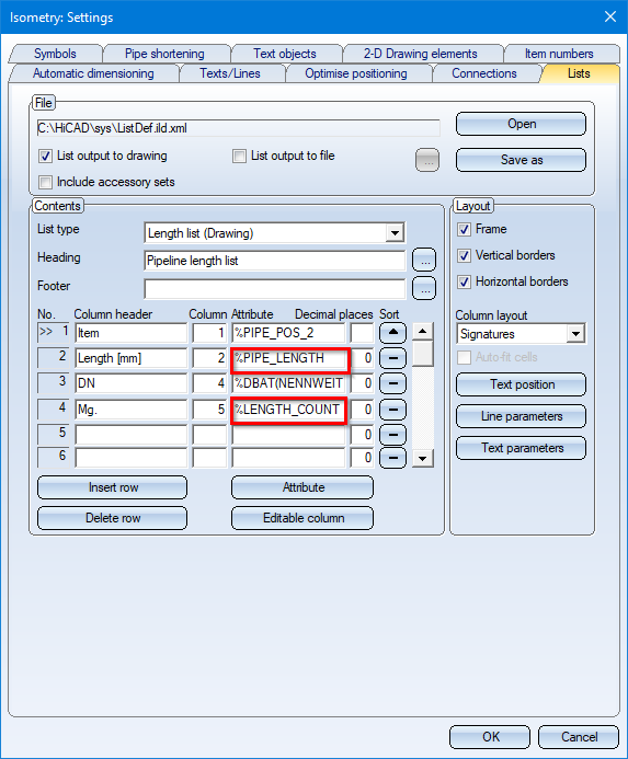
%PIPE_LENGTH |
Returns the insertion length plus the length allowance |
|
%LENGTH_COUNT |
Counts pipes of the same length, where insertion length plus length allowance must be equal. |
In the list settings, these text keys are normally used as shown below:
Isometric drawings and Pipe spool drawings - Presetting editable columns
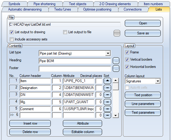
In the Settings dialogue for Isometric drawings and Pipe spool drawings, the BOMs that are to be automatically inserted into an Isometry or Pipe spool drawing can be configured on the Lists tab. In particular, individual columns of the BOM tables can be provided with the special text key %USR, which makes the column editable. This is done via the Editable column button.
Clicking on this button inserts a text key of the form %USR(XXXXXX), where XXXXXX is a randomly generated character string under which the entries are stored in the pipeline, so that they can be restored when the BOMs are generated again.
When initially creating an isometry, the editable columns were previously empty. From HiCAD 2022 you can now store a default value in the %USR text key by separating it from the random string with a colon.
Example:
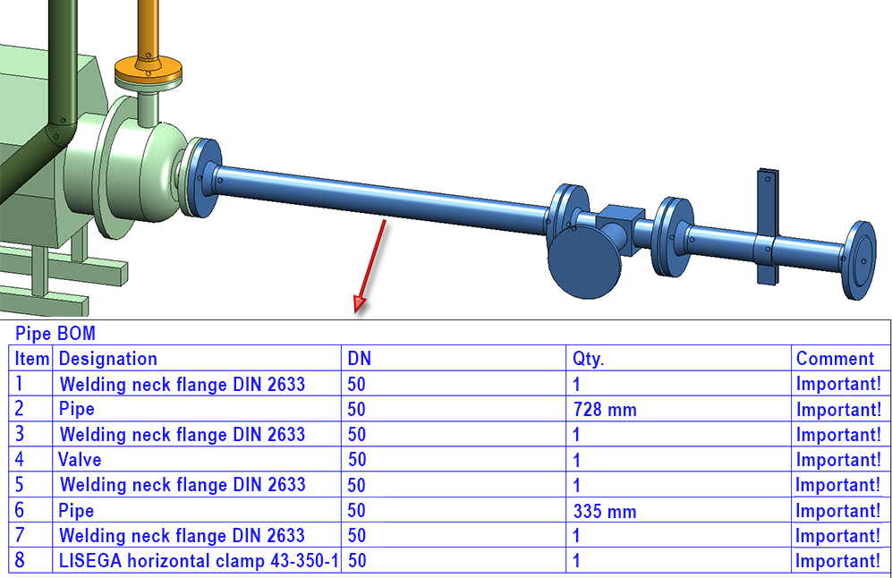
The 5th column with the title Comment is editable and as text key %USR(PTL8NR:Important!) has been entered.
The result looks as follows:
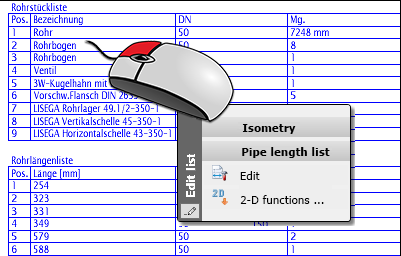
Isometric drawings and Pipe spool drawings - Editing Bills of Materials (BOMs)
As of HiCAD 2022, editing bills of materials in Isometric drawings and Pipe spool drawings and Pipe plan no longer requires a Plant Engineering licence. To edit a bills of materials table, right-click on the table and select Edit.
The ISD has made this licence change to make it more flexible for customers to fill in BOMs at a later date. For example, additional information that the actual designer does not have can be added subsequently.
The following should be noted:
The appropriate settings files must be available on the computer used to process the BOMs. The relevant settings can be found in the HiCAD sys directory in the files
- Anl3DIso.xml and
- Anl3DSpool.xml
as well as in the list configuration files. If you have not created your own configuration files, these would be the files ListDef.ild.xml and Listdef.sld.xml.
If these files do not exist, a corresponding message appears.
HELiOS database - New attributes
As described above, new part/article attributes are available as of HiCAD 2022:
|
Attribute designation |
Attribute name HELiOS |
|---|---|
|
Part colour must not be changed |
FIXED_COLOR |
|
Length allowance |
PIPE_ADDED_LENGTH |
To ensure that these attributes are also available in your HELiOS database, you must first update HELiOS for Plant Engineering. To do this, use the tool DbPlantDataImport.exe.
Revised variants JISB2301
The variants of the standard JISB2301 have been revised. The previous variants of this standard will no longer be supplied.
The following variants are no longer available:
JISB2301-99_CLASS1_45_ELBOWS.vaa
JISB2301-99_CLASS1_45_LATERALS.vaa
JISB2301-99_CLASS1_ELBOWS.vaa
JISB2301-99_CLASS1_MF_SHORT_BENDS.vaa
JISB2301-99_CLASS1_RED_MF_SOCKETS.vaa
JISB2301-99_CLASS1_REDUCING_NIPPLES.vaa
JISB2301-99_CLASS1_REDUCING_SOCKETS.vaa
JISB2301-99_CLASS1_RETURN_BENDS.vaa
JISB2301-99_CLASS1_SHORT_BENDS.vaa
JISB2301-99_CLASS1_SOCKETS.vaa
JISB2301-99_CLASS1_TEES.vaa
JISB2301-99_CLASS1_TEES_INC_BRANCH.vaa
JISB2301-99_CLASS1_TEES_RED_BRANCH.vaa
JISB2301-99_CLASS1_TEES_RED_RUN_BRANCH.vaa
JISB2301-99_CLASS1_TEES_RED_RUN_BRANCH_EQ.vaa
JISB2301-99_CLASS2_45_ELBOWS.vaa
JISB2301-99_CLASS2_45_LONG_SWEEP_BENDS.vaa
JISB2301-99_CLASS2_45_MF_ELLBOWS.vaa
JISB2301-99_CLASS2_ELBOWS.vaa
JISB2301-99_CLASS2_LONG_SWEEP_BENDS.vaa
JISB2301-99_CLASS2_M_LONG_SWEEP_BENDS.vaa
JISB2301-99_CLASS2_MF_45_LONG_SWEEP_BENDS.vaa
JISB2301-99_CLASS2_MF_ELLBOWS.vaa
JISB2301-99_CLASS2_MF_LONG_SWEEP_BENDS.vaa
JISB2301-99_CLASS2_MF_SHORT_BENDS.vaa
JISB2301-99_CLASS2_MF_SOCKETS.vaa
JISB2301-99_CLASS2_PITCHER_TEES.vaa
JISB2301-99_CLASS2_PITCHER_TEES_RED_BRANCH.vaa
JISB2301-99_CLASS2_PITCHER_TEES_RED_RUN.vaa
JISB2301-99_CLASS2_PITCHER_TEES_RED_RUN_BRANCH.vaa
JISB2301-99_CLASS2_REDUCING_MF_ELLBOWS.vaa
JISB2301-99_CLASS2_SHORT_BENDS.vaa
JISB2301-99_CLASS2_SOCKETS.vaa
JISB2301-99_CLASS2_TEES.vaa
JISB2301-99_CLASS2_TEES_INC_BRANCH.vaa
JISB2301-99_CLASS2_TEES_RED_BRANCH.vaa
JISB2301-99_CLASS2_TEES_RED_RUN_BRANCH.vaa
JISB2301-99_CLASS2_TEES_RED_RUN_BRANCH_EQ.vaa
The following variants are new:
JISB2301-99_CLASS1_45_ELBOW.vaa
JISB2301-99_CLASS1_45_LATERAL.vaa
JISB2301-99_CLASS1_45_LATERAL_.vaa
JISB2301-99_CLASS1_ELBOW.vaa
JISB2301-99_CLASS1_MF_SHORT_BEND.vaa
JISB2301-99_CLASS1_REDUCING_NIPPLE.vaa
JISB2301-99_CLASS1_REDUCING_SOCKET.vaa
JISB2301-99_CLASS1_RED_MF_SOCKET.vaa
JISB2301-99_CLASS1_RETURN_BEND.vaa
JISB2301-99_CLASS1_SHORT_BEND.vaa
JISB2301-99_CLASS1_SOCKET.vaa
JISB2301-99_CLASS1_TEE.vaa
JISB2301-99_CLASS1_TEE_INC_BRANCH.vaa
JISB2301-99_CLASS1_TEE_RED_BRANCH.vaa
JISB2301-99_CLASS1_TEE_RED_RUN_BRANCH.vaa
JISB2301-99_CLASS1_TEE_RED_RUN_BRANCH_EQ.vaa
JISB2301-99_CLASS2_45_ELBOW.vaa
JISB2301-99_CLASS2_45_LONG_SWEEP_BEND.vaa
JISB2301-99_CLASS2_ELBOW.vaa
JISB2301-99_CLASS2_LONG_SWEEP_BEND.vaa
JISB2301-99_CLASS2_MF_45_ELBOW.vaa
JISB2301-99_CLASS2_MF_45_LONG_SWEEP_BEND.vaa
JISB2301-99_CLASS2_MF_ELBOW.vaa
JISB2301-99_CLASS2_MF_LONG_SWEEP_BEND.vaa
JISB2301-99_CLASS2_MF_SHORT_BEND.vaa
JISB2301-99_CLASS2_MF_SOCKET.vaa
JISB2301-99_CLASS2_M_LONG_SWEEP_BEND.vaa
JISB2301-99_CLASS2_PITCHER_TEE.vaa
JISB2301-99_CLASS2_PITCHER_TEE_RED_BRANCH.vaa
JISB2301-99_CLASS2_PITCHER_TEE_RED_RUN.vaa
JISB2301-99_CLASS2_PITCHER_TEE_RED_RUN_BRANCH.vaa
JISB2301-99_CLASS2_REDUCING_MF_ELBOW.vaa
JISB2301-99_CLASS2_SHORT_BEND.vaa
JISB2301-99_CLASS2_SOCKET.vaa
JISB2301-99_CLASS2_TEE.vaa
JISB2301-99_CLASS2_TEE_INC_BRANCH.vaa
JISB2301-99_CLASS2_TEE_RED_BRANCH.vaa
JISB2301-99_CLASS2_TEE_RED_RUN_BRANCH.vaa
JISB2301-99_CLASS2_TEE_RED_RUN_BRANCH_EQ.vaa
JISB2301_Pipe.vaa
For easy transfer to your database the parts are listed in the JISB2301.lst list in the PlantParts directory. Use the Part Data Synchronisation function for transfer.
