
Project: HiCAD Steel Engineering
If, for the connections:
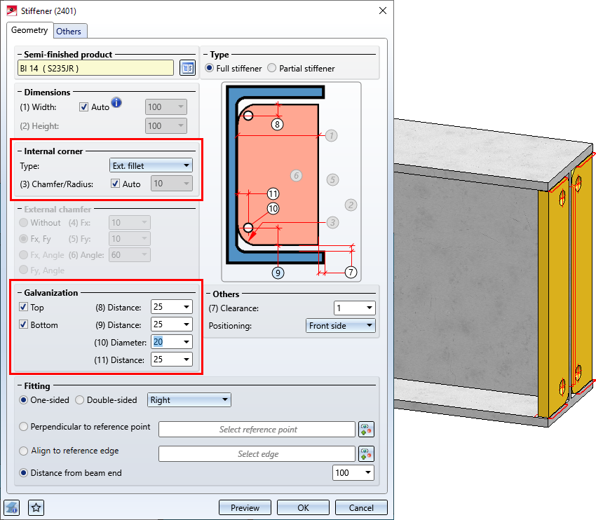
Ext. fillet is selected in the Type field under Internal corner when creating the stiffeners, then you can determine from SP1 whether the stiffeners are to be provided with holes for galvanisation.
By activating the checkboxes, determine which holes - top and/or bottom - are to be created and enter the hole diameter as well as the minimum distance to the web and flange.
From SP 1 onwards, the Edit connection/Design Variant  function remains active after changing a connection or a Design Variant. This means you can directly edit another connection without having to call up the function again. Simply identify an edge of the connection or Design Variant.
To end the function, press the middle mouse button.
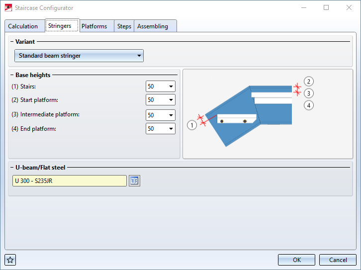
From SP1 onwards the Staircase Configurator offers elongated plates as stringers for staircases.
In addition to platforms at the stair start and stair end, several intermediate platforms are now possible. It should be noted that intermediate platforms must be added depending on the DIN standard. For example, according to DIN 18065, a maximum of 18 steps without intermediate platforms is possible for building staircases. This means that the staircase may have to be divided into several staircase segments, whereby an intermediate platform must be installed between two staircase segments.
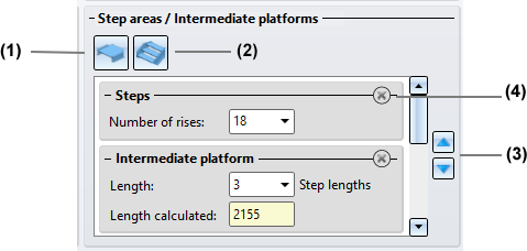
(1) Click on  to insert an intermediate platform. Enter the length of the platform in step lengths. Note that the last element in this area must be a stair segment and that several platforms must not follow each other.
(2) Click on  to insert a stair segment (steps). Enter the number of rises. Note that there must always be a platform between two stair segments.
(3) Click on the delete symbol to remove a stair segment or an intermediate platform.
(4) Use the arrow symbols to change the order of the stair segments and intermediate platforms.
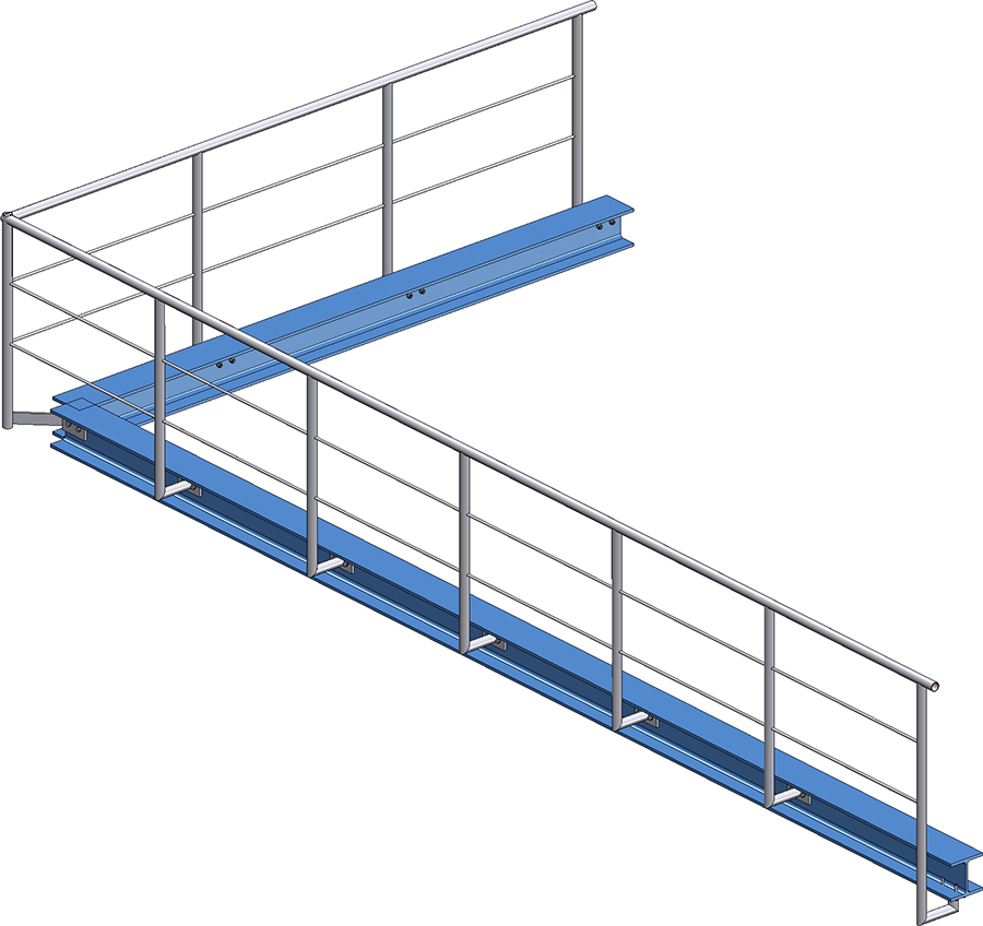
Railing with lateral connection of the start, corner and intermediate posts and connection from bottom for the end post
Please note the following when selecting the post connections: It is only possible to combine the variants Post connection, lateral and Post connection, bottom. If, for example, you have selected the variant Post connection, lateral for a corner or intermediate post and the variant Post connection, top for the start or end post, then the installation is not possible and a corresponding error message appears, e.g.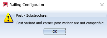
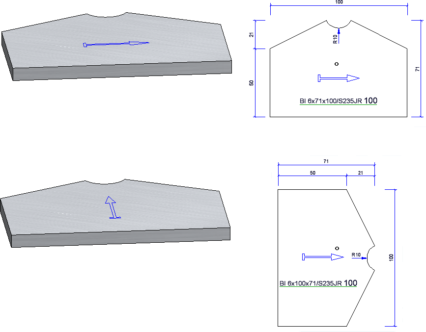
As with Sheet Metal parts, the calculation of the length and width of Steel Engineering beams now also takes into account whether a processing direction is assigned to the plate.
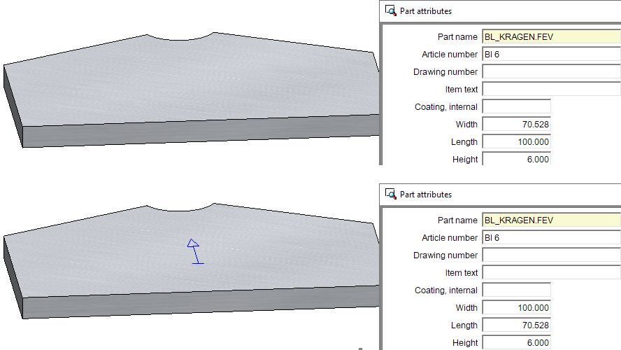
The processing direction also affects the position of the plate in the workshop drawing.
When installing prototype beams, an article master assigned to the beam in the catalogue editor was not taken over until now, since the dimensions can be changed individually during installation. For this reason, two new functions are available as of SP1:
 Prototype beams from catalogue
 Sub-part, Prototype from catalogue
In contrast to the previous functions for prototype beams, here prototype beams from the catalogue are installed, whose dimensions (except for the total length) cannot be changed in the dialogue. If assigned, the article master is also taken over.
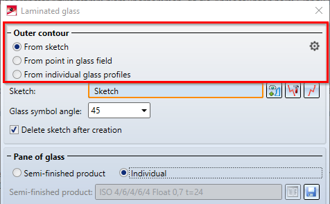
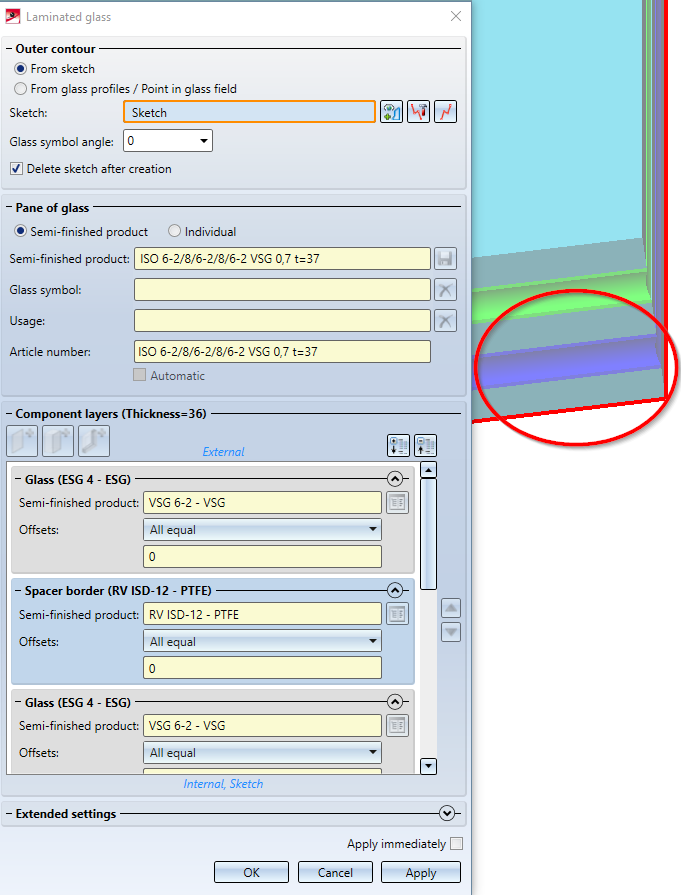
In the Laminated glass dialogue window, the three options From sketch, From point in glass field and From individual glass profiles are now directly available for selecting the outer contour. The functions behind these points were already available before, but some of them could only be accessed via the context menu. Now they can be selected directly in the dialogue window:
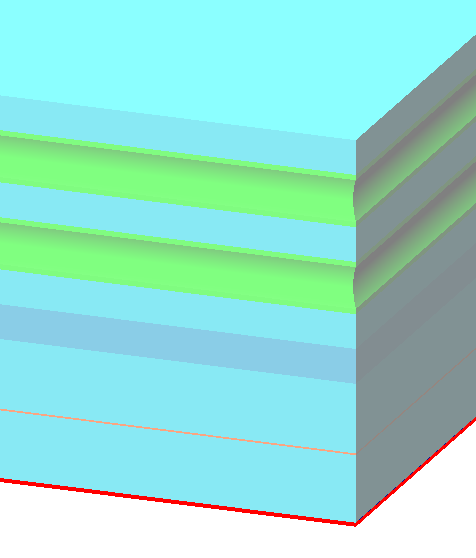
The colours in which the individual layers of a laminated glass are displayed in the preview view in the drawing have been unified. Glass panes are now always displayed in blue. If several glass panes follow one another directly, a slightly different shade of blue is used alternately. Foils and spacers are displayed in green. If a layer is selected in the Laminated glass dialogue window, it is highlighted in dark blue.
The Excel template HiCAD_Stahlbau has been extended by another worksheet: Shipping list, short, with image. This shows the same information as Shipping list, short, but additionally contains a picture of the parts.
see also Report Manager - What's new?
In the Part attributes masks, fields with a light yellow background are blocked for manual entries. This applies, for example, to the usage type. Here you can only select a usage type from the catalogue. As of HiCAD 2021 SP1, the content of several of these fields can now be deleted with a click on the  button.
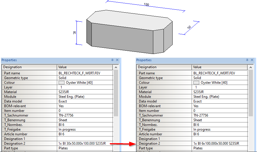
In the case of steel engineering plates, the width was previously output before the length in the Designation 2 attribute. From HiCAD 2021 SP1 this behaviour has been changed. In the same way as for Sheet Metal parts, the length is now output before the width, i.e.
Previously: {total number}x {part number}x{width}x{length} {material designation}
From SP1: {total number}x {part number}x{length}x{width} {material designation}
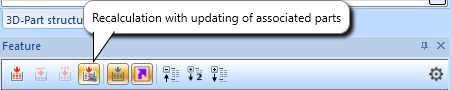
If you load drawing files created with a Version older than HiCAD 2021 SP1, you must perform a feature recalculation of the plates to adapt the Designation 2 attribute.
To update connections, you can also use the feature function Recalculation with updating of associated parts  , which can be found in the toolbar of the Feature window in the ICN.
For the Strap joint (2310) with stiffener, a second stiffener can be optionally installed. The Stiffener tab has been extended accordingly.
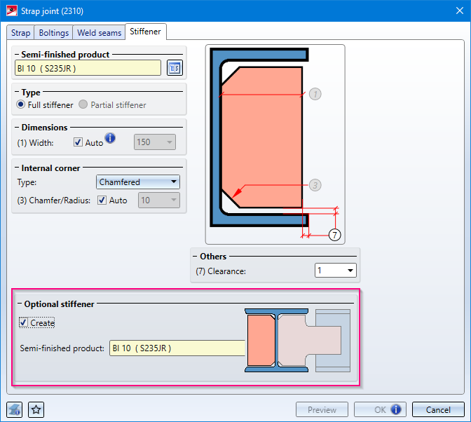
The Type selected under Internal corner is used for the optional stiffener. If the stiffener is chamfered, for example, this also applies to the optional stiffener..
(1) Stiffener, (2) Optional stiffener
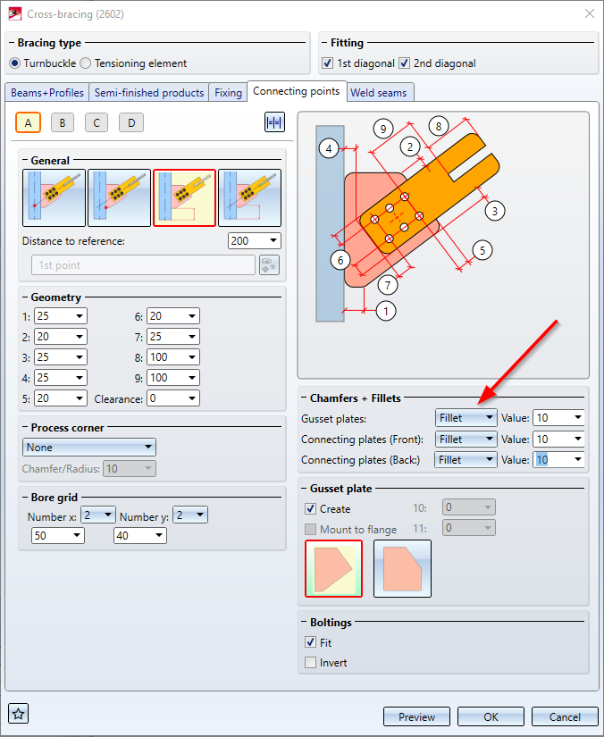
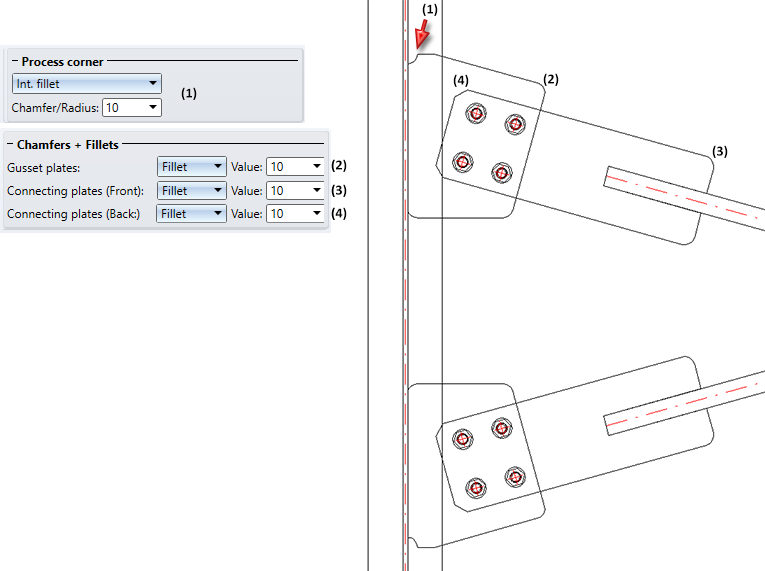
Gusset plates and connecting plates created for cross-bracings could previously only be filleted. As of HiCAD 2021, chamfering is now also possible here. This affects
The dialogue windows have been adapted accordingly.
For the connection Base plate + Anchor plate (2101) , various extensions are available with HiCAD 2021.
Changed part structure
The part structure of the created parts has changed as follows:
The assembly with the shear anchor is now called Anchor plate.
The welded plate is installed as an individual part and is not assigned to an assembly as before.
Shear connector with front plate
The shear connector can now be equipped with a front plate - also rounded. The Shear connector tab has been extended accordingly.
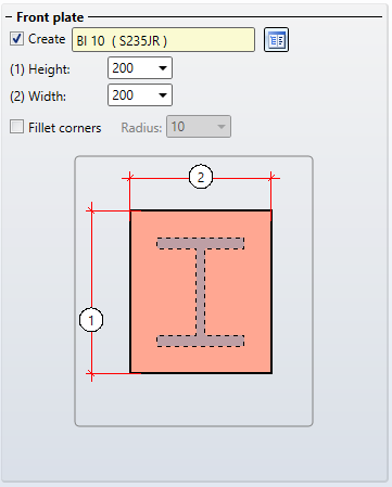
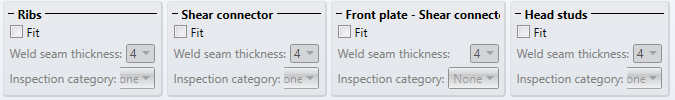
If the Create checkbox is active, you can specify on the Weld seams tab whether weld seams are to be installed between the front plate and the shear connector.
Fixing
On the Fixing tab, under Boltings (Base plate), you can select another type of fixing.
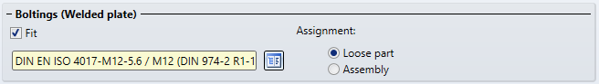
If the checkbox Fit is active, the fastening is done by a screw connection countersunk into the welded plate from below, i.e. only welded plate and base plate are screwed together.
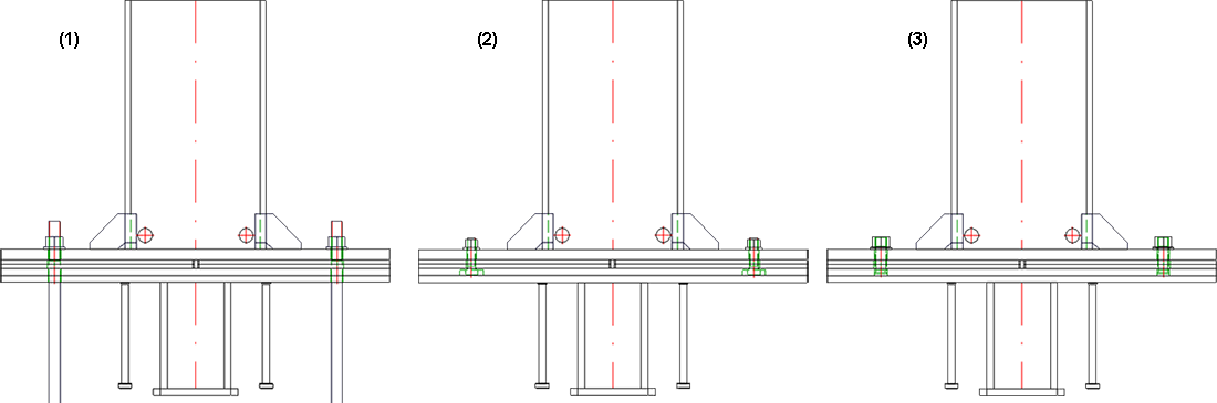
Fixing (1) Boltings (Base plate), (2) Boltings (Welded plate), (3) Threaded stud
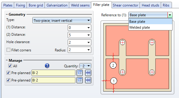
Size of the filler plates
On the Filler plate tab you can now choose whether the size of the filler plates should be based on the base plate or the welded plate.
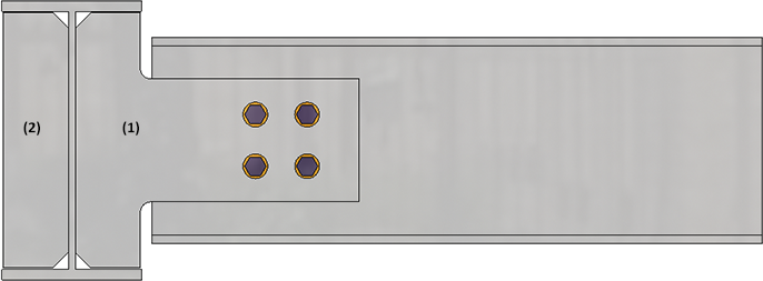
For the Cross-bracing (2601), an offset for the bore grid can now be specified on the Connecting points tab and thus influence the position of the bore grid.
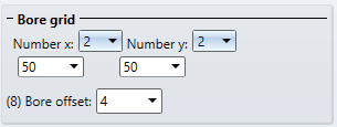
The default setting is 0, i.e. the centre of the bore or bore grid lies on the centre axis of the diagonal bracing profiles. In certain situations, for example with L-profiles, this is often not desired. In such cases, the position of the bore grid can be influenced by specifying an offset.
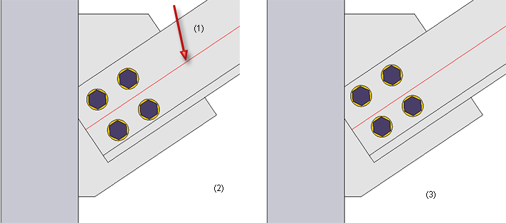
(1) Centre line of L-profile, (2) Without offset, (3) With offset
The catalogue Factory standards > Roof Wall Facade > Room-closing profiles now contains the following new sandwich elements for roofs and walls by the company Kingspan:
In this context, the QuadCore® rigid foam from Kingspan has been added to the Duromere table in the Materials > Plastics catalogue.
See also Catalogue Editor - What's New?
The algorithm for creating notches on CUTOUTs has been revised and now delivers better results than in previous versions.
This initially only affects newly created notches; notches created with previous versions remain at the previous level even after a feature recalculation. To have these notches calculated with the new algorithm, you must delete them and then create them again.
When exchanging beams, the material of the beam is not changed, provided that the material of the beam to be exchanged is available for the exchanged beam.
An example:
A drawing contains a type I 80 beam with material S355J0. This beam is to be exchanged with an IPE beam. In this case, the material S355J0 is automatically set when selecting the exchanged beam in the catalogue. If the material for the exchanged beam is not available, the standard material of the exchanged beam is set.
For dividing beams along a direction the function Divide along direction  is now available at Steel Engineering > Lengthen > Divide. This function essentially works in the same way as the 3-D function 3-D Standard > Process > Trim > Divide along direction function, except for the following differences:
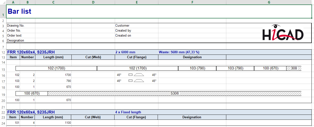
In practice, model drawings often contain beams, e.g. purchased parts, which are ordered for the production with a fixed length. These beams should not appear in the bar list or must be shown separately.
In HiCAD this can now be regulated via the attribute Fixed length (%FIXLEN), which must be assigned to the corresponding beams. If this attribute has the value 0 or is not set at all, the fixed length is not taken into account in the bar list. If the value is 1, then these beams are listed separately in the bar list.
By default, the attribute is not set, i.e. it is not included in the attribute masks. If you want to use this attribute, you must manually extend the attribute mask for beams by adding the files
accordingly.
In case of a new installation of HiCAD (from HiCAD 2021), the attribute fixed length is automatically evaluated when creating Excel BOMs with the configuration file HiCAD_Stahlbau.2600.0. For this purpose, the system file for the BOM item data rm_h_exportpart.hdb must be supplemented with the line
<H>::TEXT=""::ATTR="%FIXLEN"::TYP="INTEGER"::ALIGN="LEFT"::EDIT="NO"
has been adapted accordingly. In the case of an update installation, you may have to add this line to the file manually.
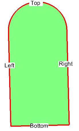
If you construct a laminated glass with an individual layer structure, the corresponding layer is now also highlighted in colour in the drawing when you select a layer in the Laminated glass dialogue window.
During insertion / editing of laminated glass panes, the directions left, right, top and bottom are now displayed in the drawing on the glass.
In order to be able to influence the alignment of the glass and thus the angle of rotation of the glass symbol, the option Glass symbol angle has been added to the dialogue. With this option the alignment can be adjusted exactly to the degree. The direction display in the construction is adjusted accordingly.
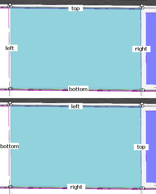
Top: Glass symbol angle 0; Bottom: 90.
It is now possible to automatically generate an article number from the layers used in the individual construction of a laminated glass panel. For this purpose, there is a new checkbox Automatic in the dialogue window Laminated glass under the Article number field. If this is activated, the article number is generated automatically by combining the designations of the individual layers separated by a separator to form an article number.
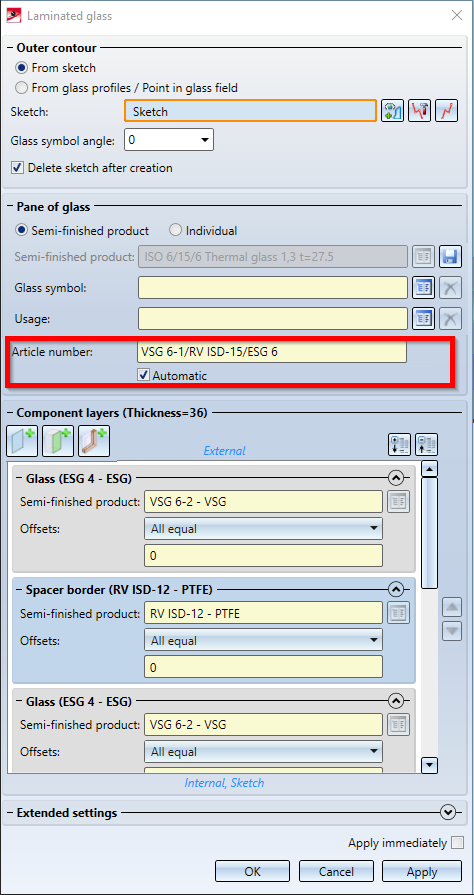
The character "/" has been set as separator; this can be changed in the Configuration Editor at Steel Engineering > Products > Laminated glass pane > Separator for auto-generated article number of a laminated glass pane if desired.
When working with the 3-D grid function, grid annotations are now inserted on both sides.
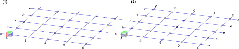
(1) up to HiCAD 2020, (2) from HiCAD 2021 onwards
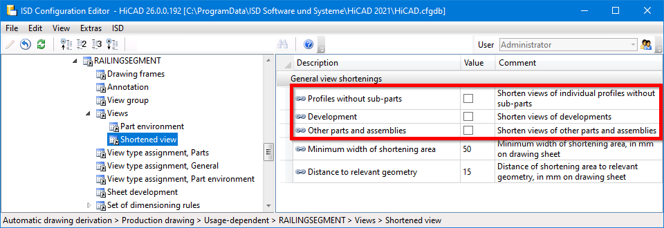
The configuration RAILINGSEGMENT for railings in the drawing derivation has been changed. Views are now not automatically shortened here. For this purpose, in the Configuartion Editor at
Automatic drawing derivation > Production drawing > Usage-dependent > RAILINGSEGMENT > Views > Shortened view
the checkboxes have been deactivated.
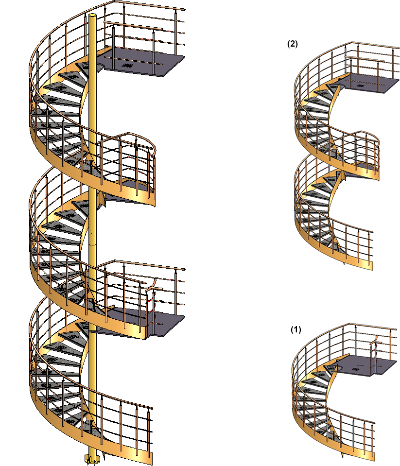
With the new Spiral staircase tool in the Civil Engineering functions docking window the first draft of a configurator for spiral staircases is available. However, it does not yet have the full range of functions yet. In future HiCAD versions, this tool will be expanded into a fully functional configurator with different variants for newels, stringers, platforms, railings and steps, special dimensioning rules for drawing derivation, etc.
However, the current configurator can already be used to visualise spiral staircases, for example in Plant Engineering drawings as a placeholder for such prefabricated staircases.
The image below shows a spiral staircase with two floors (1) and (2), which has been created with the default settings of the ISD.

|
© Copyright 1994-2021, ISD Software und Systeme GmbH |
Data protection • Terms and Conditions • Cookies • Contact • Legal notes and Disclaimer