Project: HiCAD Sheet Metal
With the new function Connect sheets  (Further functions > Extras
  > ...) you can connect bent sheets with an own feature log. The prerequisite is that the sheet thickness, the material or semi-finished product match and the base sheet was created with one of the following functions:
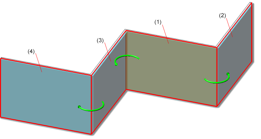
First activate a sheet and then call the function. Then select the sheets to be attached. Finish the selection by pressing the middle mouse button.
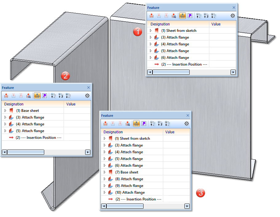
The feature log of the added sheets is hung under the log of the active sheet and the added sheets are deleted. The creation feature and the other feature steps such as Attach flange are retained.
In the part structure, the flanges and bend zones are also attached to the active sheet. The added sheets are deleted from the part structure.
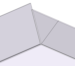
(1) Active sheet; (2) Added sheet; (3) Feature log after the connection. The feature of the second sheet is added.
The automatic search on one side has been added to the function New sheet from surface  . This means that sheet-like parts that have been imported via 3-D interfaces, for example, can only be searched on one side of the surface..
(1) Start surface (base sheet) for automatic search on one side  ; (2, 3, 4) connected sheets
The tab Milling+Folding - Extended has been added to the Extended settings for sheet development. The following options have been moved from the Milling+Folding tab:
New is the option
In acute corners, the outer contour cannot be milled exactly with the standard milling cutter. In practice, a cutter with a smaller diameter is used here. In the development calculation, paths for the treatment of acute corners can optionally be generated on a separate layer.
To display the path, check the option  Paths for acute inner corners. Then enter the angle up to which the path is to be generated. You can also set the path length, layer, color and line type.
The path does not lie exactly on the outer contour (distance of 0.01 mm) to prevent it from disappearing during export.
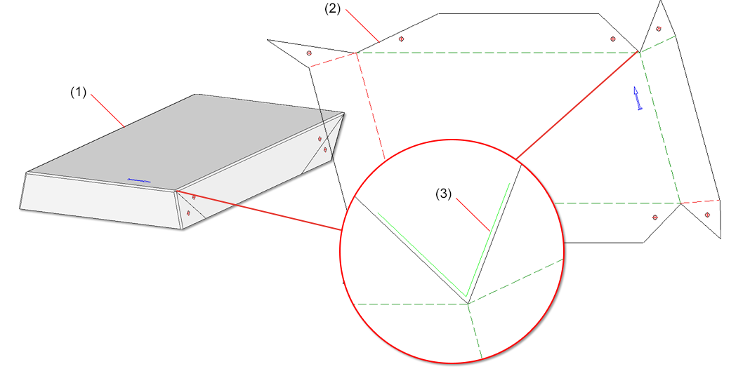
(1) Sheet metal part, (2) Development, (3) Enlargement of the path for the acute inner corners with a path length of 0.3
The view from the left has been deactivated in the default settings for Sheet Metal parts in the drawing derivation. This affects the setting at Automatic drawing derivation > Production drawing > Usage-dependent > DEFAULT(KANTBLECHE) > View type assignment, Parts > View types: Sheets.
This means that the view from the left is not automatically generated for Sheets Metal parts in the drawing derivation.
Due to the complete revision of the function New sheet from surface  you can now construct a new sheet metal part with bending zones or milled edge zones from the surfaces of a 3-D part. After selecting the function, the following dialogue window appears.
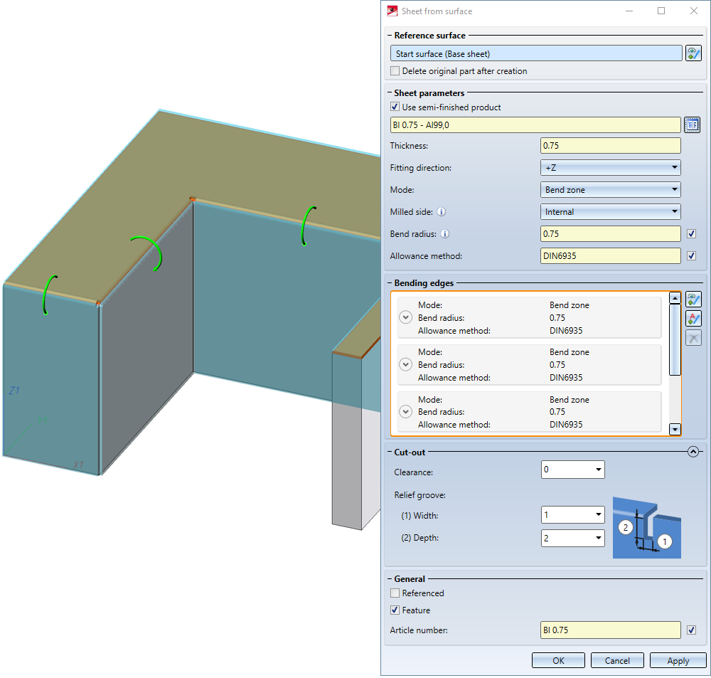
If you want to identify another surface, select the  icon for identifying the base surface in the Reference surface area.
If you choose a semi-finished product ![]() from the Catalogue Editor
from the Catalogue Editor  , the sheet thickness is not requested. The Thickness, the Material and, if applicable, the Article number are then taken from the Catalogue Editor for the sheet metal. In the General area you can also change the article number for the selected semi-finished product. If you want to take over the bending radius, which is only evaluated in the Mode: Bend zone, from the Catalogue Editor, activate the
 ![]() From semi-finished product checkbox next to the input field of the bend radius. In the Bending edges area, you can also change the bend radius individually afterwards for selected semi-finished products.
From semi-finished product checkbox next to the input field of the bend radius. In the Bending edges area, you can also change the bend radius individually afterwards for selected semi-finished products.
The Fitting direction determines the side to which the sheet thickness is applied. The surface of the 3-D part serves as a reference.
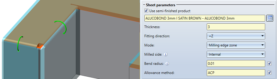
In the Mode field you can choose between Bend zone and Milling edge zone. The milled edge zone is used in practice for composite panels. The Milled side, which is only evaluated in the Mode: Milling edge zone, refers to the position of the 3-D part. The setting is adopted as a default for the complete sheet metal part and can be changed individually in the Bending edge area or via the feature for each milled edge zone.
.This area is used to select the bending edges and for individual settings. Deviations from the default setting that you have set in the Sheet parameters area can be made here.
You can edit the selection of bending edges with the following icons:
|
|
Use this icon to select edges or cylinder segments. |
|
|
With the AutoSearch option search, all possible bending edges are taken into account. |
|
|
The selected bending edge is removed from the list. You can select the edge in the dialogue window or in the drawing. Multiple selection is possible by selecting while holding down the CTRL key. |
If you want to change e.g. the radius or the allowance method for a bend zone, expand the area with this icon  .
.
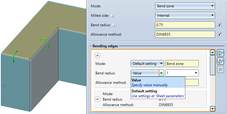
For the Bend zone the Mode, the Bend radius and the Allowance method become editable if you select Value instead of Default setting.
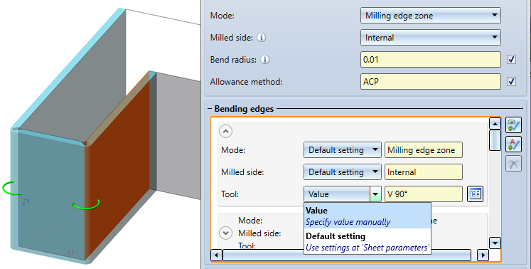
For the Milling edge zone, the Mode, the Milled side and the Tool (from the catalogue) become editable if you select Value instead of Default setting.
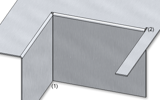
(1) Clearance, (2) Relief groove
Once you have entered all the necessary data, the new sheet can be inserted. If you select Apply or press the middle mouse button (MMB), the sheet metal part will be inserted, but the dialogue window remains open - in contrast to OK.
![]() Please note:
Please note:
Incorrect entries are marked with this symbol  . If you move the cursor over the symbol an error message will be displayed.
If the function cannot be executed with the entered data, this symbol  . appears on the OK button. Here, too, move the cursor over the symbol to display the error message.
(1) Sheet Metal part with bend zone
(2) Sheet Metal part with milling edge zone
With the Bend zone tooling  function you control the assignment of bending tools to bend zones. In the HiCAD Sheet Metal module, the angle, the bending radius and the allowance method are defined for bend zones. In practice, the bend radius depends, for example, on the material, the thickness and also the bending tools used. To take this into account, you must first enter the data of the tools in the Catalogue Editor. Then the function can be called and the data stored in the catalogue can be assigned. The data set in this way can then be output in the development.
After calling the function, the input mask appears. The bend zones of the active part are displayed. If you want to identify another sheet metal part, select the icon  for identification in the Sheet area.
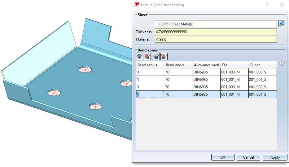
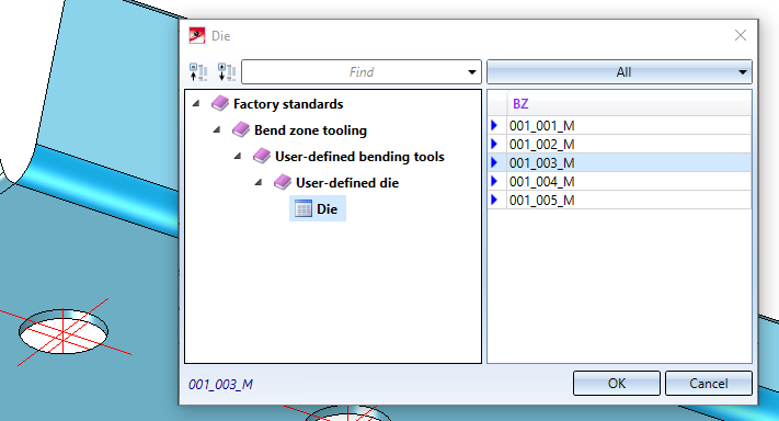
To assign the tools, activate the bend zone. If you hold down the CTRL key, you can activate several bend zones by clicking on them. Then select the icon for e.g. Die  or Punch
  . The data stored in the catalogue are then offered for selection.
If you have entered all the necessary data, the assignment can be applied.
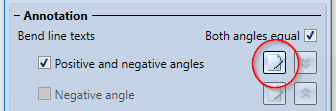
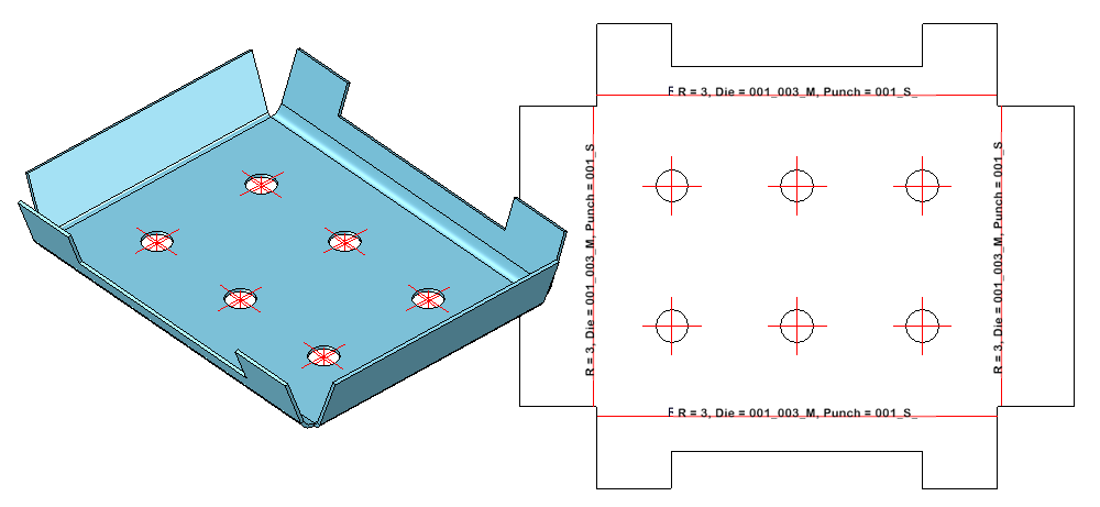
The bending tools Die and Punch defined in the Bend zone tooling can be displayed in the bend line text of the development.
The selection is made in the Development settings dialogue when editing the bend line texts.
If a bend zone tooling exists for the bend zone, the names of these tools can now be inserted into the bend line text, via the attributes Die and Punch in the Text Editor.
When installing the design variant Sheet corner with stiffener, you now have several options to choose from when using the stiffener.
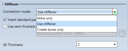
|
Mitre only |
|
|
Use stiffener |
Use of stiffener with the option Insert standard parts
Use of stiffener without the option Insert standard parts |
|
Create bores only |
|
The ISD default setting is that standard parts are created, i.e. the checkbox is active. If the checkbox is inactive, the standard parts are not listed in the bill of materials. The option is only active if you have selected Use stiffener in the connection mode.
In the catalogue Factory standards > Composite panels, groove form the table Standard groove form has been extended. This table is used for attaching and folding of flanges
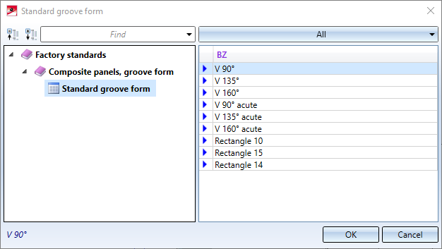
The new milling cutters for acute-angled attachments or foldings are intended for 2-D drawing. There, cassettes and trays are represented as simplified paper models. If you design in the paper model and want to use the groove shapes for acute-angled attachments or foldings automatically, you have to change the priority in the catalogue editor. E.g. groove form V 90° gets a 6 in column SORT and V 90° acute gets a 1. If you have set the check mark  for Tool when bending, a tool is automatically loaded depending on the selected bending angle and the assignment in the catalogue (column SORT).
In HiCAD, the milling cutters with the priority (SORT column) 1-3 and 10 are used by default.
|
Bend angle |
Groove form |
SORT (assignment to bend angle) |
|
≤ 90° |
V 90 ° |
1 |
|
91° bis 135° |
V 135° |
2 |
|
136° bis 160° |
V 160° |
3 |
|
161° bis 180° |
Rectangle 10 |
10 |
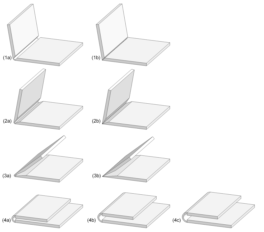
(1a) V 90°, (1b) V 90° acute ,
(2a) V 135°, (2b) V 135° acute ,
(3a) V 165°, (3b) V165° acute ,
(4a) Rectangle 10, (4b) Rectangle 14, (4c) Rectangle 15
The ABWEditor (Development Editor) from the EXE directory of your HiCAD installation is available for editing or creating the allowance methods for sheet metal developments. You can now also call the Editor via the Sheet Metal Ribbon tab, at Sheet development > AllMet > ABWEditor  .
.
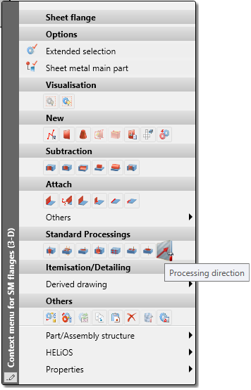
If you activate a sheet metal flange with the right mouse button, the function for creating a Processing direction  now appears in the context menu.
Purchased/factory standard parts and moulding tools are also placed in the model drawing via the Fitting CS of the corresponding KRA file or via three isolated and named points defined in the KRA file (Point 1 for the origin, Point 2 for the X-direction, Point 3 for the Y-direction). If neither these points nor a Fitting CS are defined, a corresponding message appears from HiCAD 2021 onwards.
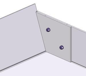
Since composite panels are usually bonded or riveted, you now have the option of inserting bores in the Welded corner function. The prerequisite is the use of a composite panel for the semi-finished product.
If you have selected a composite sheet for Semi-finished products, you can activate the option Create bores and select a bore diameter.
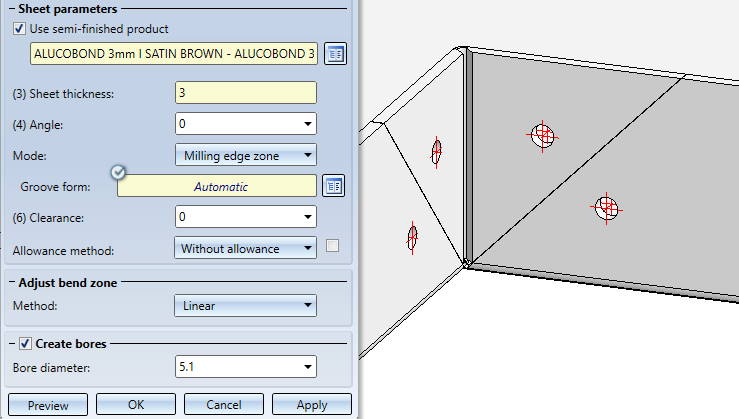
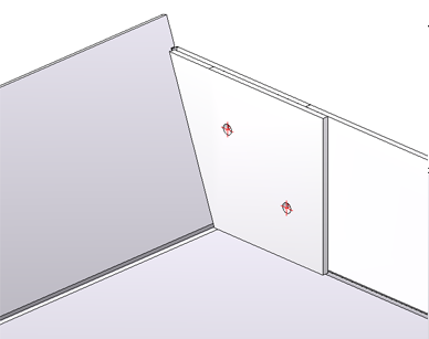
If you have activated Milling edge zone as a mode when installing the welded corner, the outer contour of the sheet in the area of the bonded / riveted edges is excluded for the milling cutter.
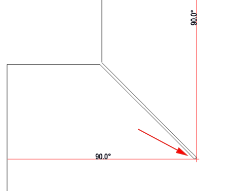
Development with subtraction for milling cutter
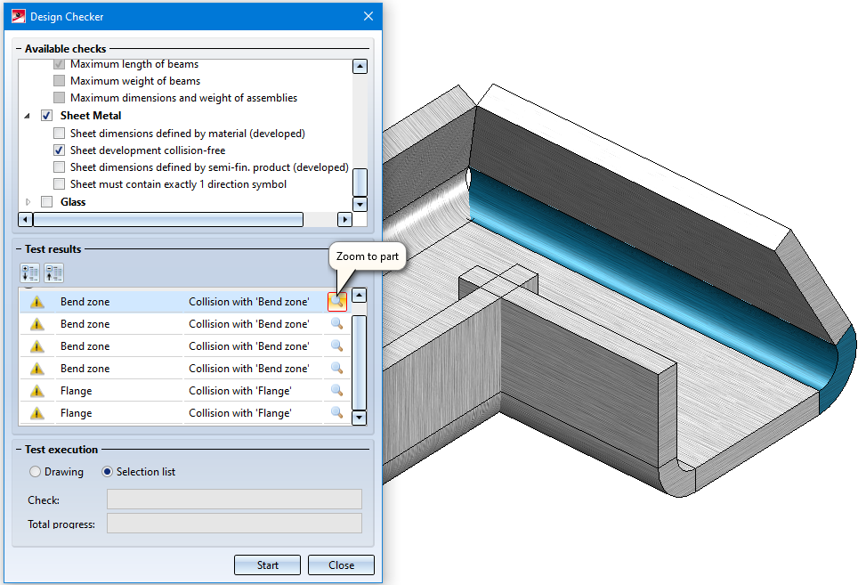
The Design Checker  can be used to check sheet metal parts for collisions between flanges or bend zones during a development or bending simulation.
As of HiCAD 2021, it is now also possible to export sheet metal developments by views. To do this, use the function 3-D Export (STEP, 3D PDF...) by views  in the context menu of a view. To activate the menu, right-click on the view frame.
This applies to STEP and all CADFIX formats.

HiCAD Sheet Metal • General Notes on Sheet Metal Processing • Overview of Functions (3-D SM)
|
© Copyright 1994-2021, ISD Software und Systeme GmbH |
Data protection • Terms and Conditions • Cookies • Contact • Legal notes and Disclaimer