
Project: HiCAD Sheet Metal
Sheet Metal > New > FromSur
With the function New sheet from surface you can construct new sheet metal parts by assigning a sheet thickness from the surfaces of a 3-D part. After selecting the function, the dialogue window appears.
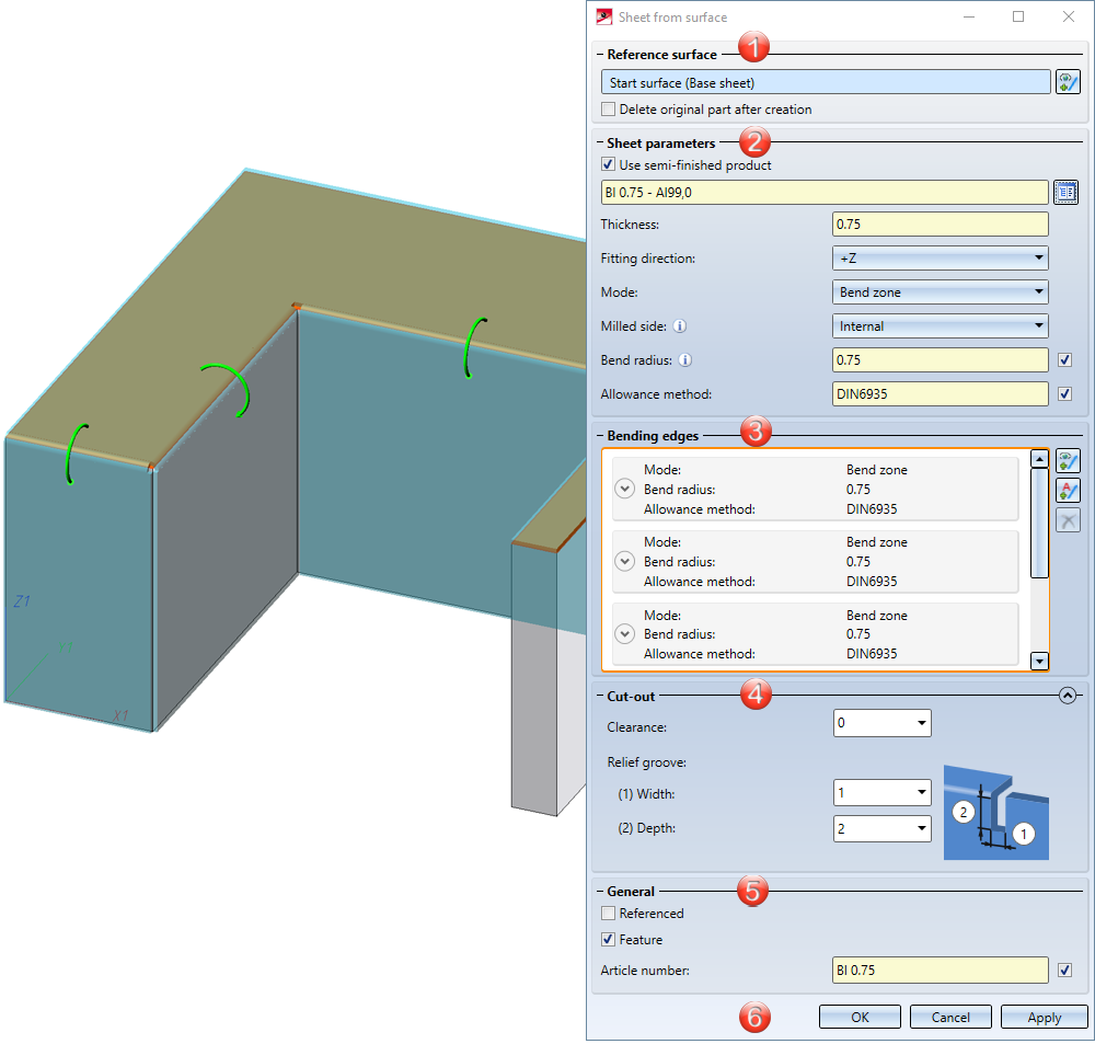
4. Cut-out
5. General

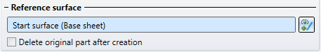
If you want to identify another surface, select the  icon for identifying the base surface in the Reference surface area.
The option Delete original part after creation deletes the 3-D part as soon as the sheet has been created from it. The entry for the 3-D part is then also deleted in the ICN.
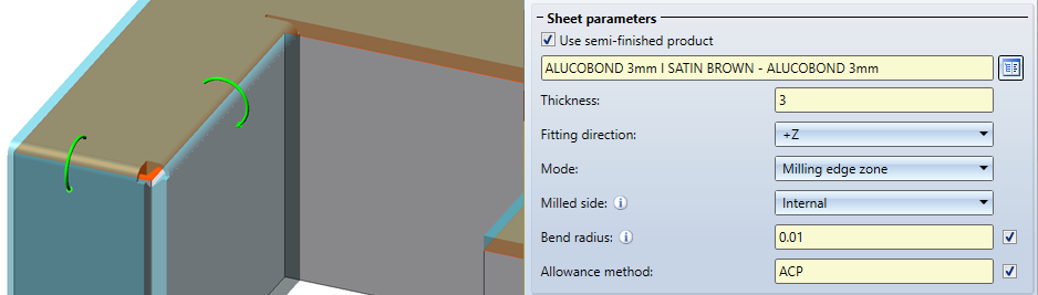
Enter the sheet Thickness, Fitting direction and Mode (Bend zone or Milling edge zone) in the dialogue window.
If you choose a semi-finished product ![]() from the Catalogue Editor
from the Catalogue Editor  , the sheet thickness is not requested. The Thickness, the Material and, if applicable, the Article number are then taken from the Catalogue Editor for the sheet metal. In the General area you can also change the article number for the selected semi-finished product. If you want to take over the bending radius, which is only evaluated in the Mode: Bend zone, from the Catalogue Editor, activate the
 ![]() From semi-finished product checkbox next to the input field of the bend radius. In the Bending edges area, you can also change the bend radius individually afterwards for selected semi-finished products.
From semi-finished product checkbox next to the input field of the bend radius. In the Bending edges area, you can also change the bend radius individually afterwards for selected semi-finished products.
The Fitting direction determines the side to which the sheet thickness is applied. The surface of the 3-D part serves as a reference.
In the Mode field you can choose between Bend zone and Milling edge zone. The milled edge zone is used in practice for composite panels. The Milled side, which is only evaluated in the Mode: Milling edge zone, refers to the position of the 3-D part. The setting is adopted as a default for the complete sheet metal part and can be changed individually in the Bending edge area or via the feature for each milled edge zone.
In order to obtain the blank (development) of the modelled sheet metal part, HiCAD offers you the development according to different calculation methods (allowance method), which take into account the material-dependent length change of the workpiece that occurs during bending. HiCAD offers the allowance methods which are also common in practice. A certain calculation method is represented by a system file. These files are prepared as examples, but in practice each user will store one or more methods in this way. Activate the ![]() From semi-finished product checkbox next to the Allowance method if you want to take over the file from the Catalogue Editor.
From semi-finished product checkbox next to the Allowance method if you want to take over the file from the Catalogue Editor.
.This area is used to select the bending edges and for individual settings. Deviations from the default setting that you have set in the Sheet parameters area can be made here.
You can edit the selection of bending edges with the following icons:
|
|
Use this icon to select edges or cylinder segments. |
|
|
With this automatic search, all possible bending edges are taken into account. |
|
|
With this automatic search, only the side of the start surface (base sheet) will be taken into account. |
|
|
The selected bending edge is removed from the list. You can select the edge in the dialogue window or in the drawing. Multiple selection is possible by selecting while holding down the CTRL key. |
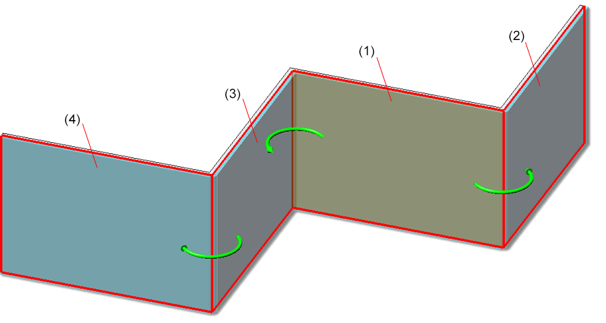
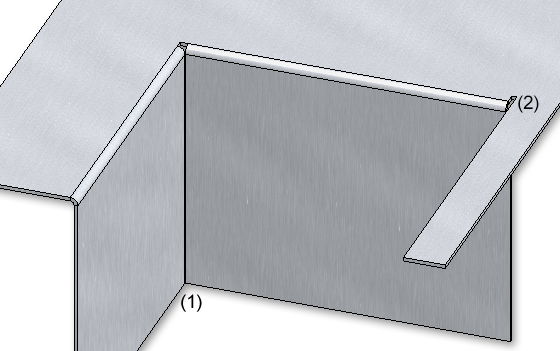
(1) Start surface (base sheet) for automatic search on one side  ; (2, 3, 4) connected sheets
If you want to change e.g. the radius or the allowance method for a bend zone, expand the area with this icon  .
.
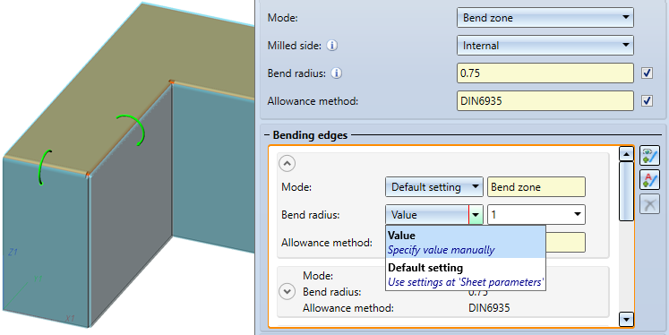
For the Bend zone the Mode, the Bend radius and the Allowance method become editable if you select Value instead of Default setting.
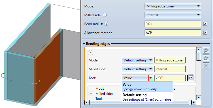
For the Milling edge zone, the Mode, the Milled side and the Tool (from the catalogue) become editable if you select Value instead of Default setting.
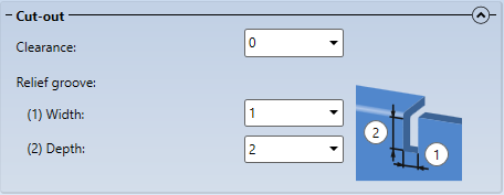
(1) Clearance, (2) Relief groove
A frequently used part should be saved referenced. The part is then additionally saved as an individual part at the end of the function sequence and is not permanently integrated into the drawing. If the individual part is changed, you can update the part in the model drawing .
To deactivate the Feature when creating the sheet metal part, deactivate the same-named checkbox ![]() . By default the feature checkbox is active
. By default the feature checkbox is active ![]() .
.
The name of the sheet metal part is generated automatically. You can overwrite it in the Article number input field.
Once you have entered all the necessary data, the new sheet can be inserted. If you select Apply or press the middle mouse button (MMB), the sheet metal part will be inserted, but the dialogue window remains open - in contrast to OK. This way you can change the data and construct another sheet metal part with Apply. If you leave the dialogue window with Cancel, the function will be cancelled without any part insertion or modification taking place.
![]() Please note:
Please note:
Incorrect entries are marked with this symbol  . If you move the cursor over the symbol an error message will be displayed.
If the function cannot be executed with the entered data, this symbol  . appears on the OK button. Here, too, move the cursor over the symbol to display the error message.
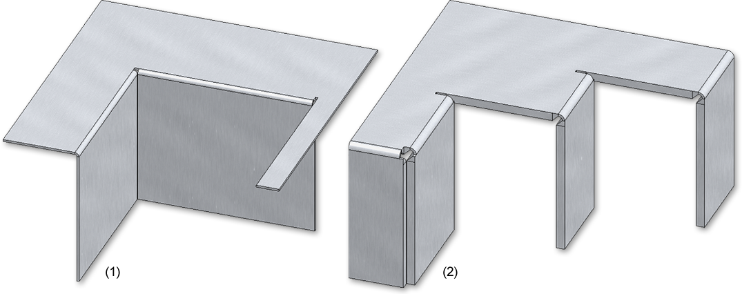
(1) Sheet metal part with bend zone
(2) Sheet metal part with milling edge zone
![]() Please note:
Please note:
Only the surface of the 3-D part is used for the generated sheets/flanges. If there are countersunk bores in the 3-D part, for example, only the outermost (largest) diameter is included in the sheet to be created. In the same way, for subtractions or additions, only the outermost surface is included in the new sheet.

|
© Copyright 1994-2021, ISD Software und Systeme GmbH |
Data protection • Terms and Conditions • Cookies • Contact • Legal notes and Disclaimer

